Table of Contents
Advertisement
Available languages
Available languages
Quick Links
FAIRCHILD T6000 Electro-Pneumatic Transducers
Installation, Operation & Maintenance Instructions
GENERAL INFORMATION
The Model T6000 can be mounted directly onto a flat surface using two 10-32 screws.
The Model T6000 is supplied with a Mounting Kit 16799-1 for Panel or Wall Mounting. For detailed mounting
information, see page 3, Figures 6, 7 & 8.
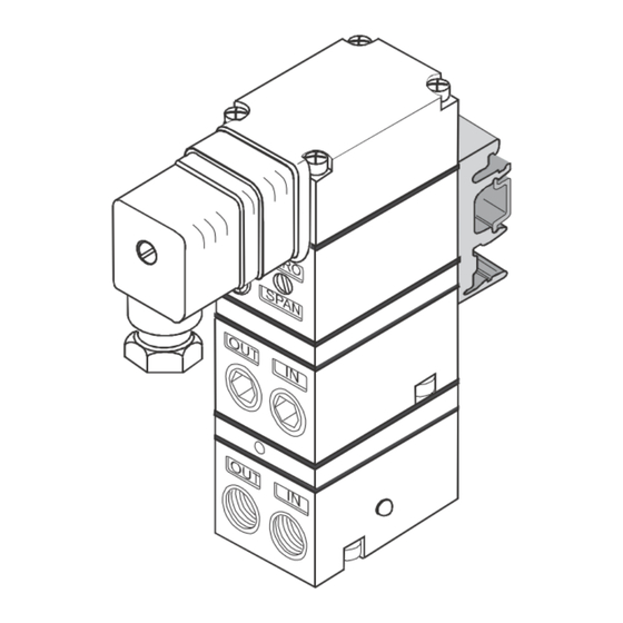
Figure 1. TA6000 Outline
Dimensions
Extended Range
Note: Unused IN and OUT
Ports are plugged (typical
Figure 2. TT6000 Outline
Dimensions
Figure 3. TD6000 Outline
Dimensions
Standard and Extended Ranges
1 33/64
38.7
ZERO
3 43/64
93.3
SPAN
Orifice
OUT
IN
5 11/64
131.5
Do Not
OUT
IN
Remove
Plugs
(typ.)
1/4 NPT
Outlet Port (2)
(typical)
)
1 33/64
38.7
_
+
ZERO
3 43/64
SPAN
93.3
OUT
IN
5 11/64
131.5
1/4 NPT
Outlet
OUT
IN
Port (2)
(typical)
ZERO
3 5/64
SPAN
78.3
OUT
IN
4 19/32
116.5
1/4 NPT
OUT
IN
Outlet
Port (2)
(typical)
3 3/64
77.5
1/2-14
NPT
3 7/64
79.0
4 39/64
117.2
2 1/4
1/4 NPT
Inlet Port (2)
57.2
(typical)
Do Not
Remove
Plugs
(typical)
1/4 NPT
Inlet
Port (2)
(typical)
90 Alternating
Positions
Do Not
Remove
Plugs
(typical)
1/4 NPT
Inlet
Port (2)
(typical)
1
1
25.4
1/2
12.7
Vent
1 59/64
49.0
OUT
IN
Do Not
Remove
OUT
IN
Plugs
(typ.)
25/64
9.8
25/32
19.7
3 3/32
78.7
3 21/64
84.6
4 53/64
122.8
2 7/16
1 1/8
61.8
28.6
1 11/32
34.1
1 31/64
37.8
Use two
10-32
Screws for
Mounting
3 7/16
87.2
Advertisement
Table of Contents

Related Manuals for Fairchild T6000


Summary of Contents for Fairchild T6000
- Page 1 The Model T6000 can be mounted directly onto a flat surface using two 10-32 screws. The Model T6000 is supplied with a Mounting Kit 16799-1 for Panel or Wall Mounting. For detailed mounting information, see page 3, Figures 6, 7 & 8.
- Page 2 Figure 4. TR6000 Outline 3 3/32 1 33/64 Dimensions 78.7 38.7 Vent 3 43/64 Do Not 3 21/64 93.3 Remove 84.6 Plugs (typical) 5 11/64 1/4 NPT 123.5 Inlet Port (2) 4 53/64 1/4 NPT (typical) Outlet 122.8 Port (2) (typical) 82.2 Figure 5A.
-
Page 3: Installation
NOTE: The TR6000 Transducer is designed for use with the TR Rack Kit. Physically, it is the same as the The Model T6000 is supplied with a DIN Rail Mounting TT6000 (Terminal Block) Unit except that the terminal Kit 16893. For detailed information, see Figure 7. A block has been rotated to the rear. -
Page 4: Maintenance
Tighten connections securely. Avoid undersized Remove the Orifice Assembly from the unit. For fittings that will limit the flow through the transducer and cause detailed information see Figure 1 “T6000 Calibration pressure drop down stream. Configuration on page 1. -
Page 5: Full Range Operation
CALIBRATIONS / ADJUSTMENTS Reverse Acting Mode Adjustment Connect the input signal to the transducer as shown Equipment Required for Calibration: in Figure 9. • Pneumatic Supply capable of delivering up to 150 psig. • Reverse Acting Calibration-Zero • Current Supply capable of delivering up to 60 mA. 6. - Page 6 Hazardous Location Installation Special Conditions for Safe Use: ATEX Intrinisically Safe Intrinisically Safe TAEI6000, TDEI6000 & TJEI6000 series with "W" Option TTCI6000 & TRCI6000 Ex ia IIC T4 Ga (Ta = -40°C to +70°C) II 1GD CL I, Div 1, Grps ABCD T4 (Ta = -40°C to +80°C) Ex ia IIIC T135°C Da (Ta = -40°C to +70°C) Exia per drawing 18005 CI I, Div 2, Grps ABCD...
-
Page 7: Legal Notice
The information set forth in the foregoing Operation and Maintenance Instructions shall not be modified or amended in any respect without prior written consent of Fairchild Industrial Products Company. In addition, the information set forth herein shall be furnished with each product sold incorporating Fairchild's unit as a component thereof. -
Page 8: Allgemeine Informationen
Installations-, Betriebs- und Wartungshandbuch ALLGEMEINE INFORMATIONEN Das Modell T6000 kann direkt mit zwei 10-32-Schrauben auf eine flache Oberfläche montiert werden. Im Lieferumfang des Modells T6000 ist ein Montagebausatz 16799-1 zur Brett- oder Wandmontage enthalten. Detaillierte Montageanweisungen finden Sie auf Seite 3, Abbildungen 6, 7 und 8. -
Page 9: Standard Version
Abbildung 4. Außenabmessungen TR6000 3 3/32 1 33/64 78.7 38.7 Vent Entlüftung 3 43/64 Do Not 3 21/64 93.3 Remove Die Stopfen 84.6 Plugs dürfen nicht entfernt werden (typical) 5 11/64 1/4 NPT 123.5 Inlet Eingangs Port ¼“ Port (2) NPT (2) 4 53/64 1/4 NPT... - Page 10 Two 1/4” NPT Pipe Plugs Montagehalterung • 2 Stück Stopfen mit ¼” NPT-Gewinde Two 7/16” Thick Spacers (not used on T6000) 9/32 2 Stück 7/16” dicke Abstandshalter (nicht für T6000 verwendbar) Abbildung 7. Montagebausatz 16893 für DIN-Schiene (im Gerät enthalten) EN-50022 EN-50035...
-
Page 11: Wartung
Sie sich vom Ende der Verschraubung weg, um Verunreinigungen 2. Entfernen Sie den Düseneinsatz vom Gerät. des Wandlers zu vermeiden. Installieren Sie den Wandler an Nähere Angaben finden Sie in Abbildung 1 "T6000 der Luftleitung. Die Einlass- und Auslassöffnungen sind an den Kalibrierkonfiguration" auf Seite 1. - Page 12 KALIBRIERUNG / ANSCHLÜSSE Einstellen des Rückwärtsmodus Für die Kalibrierung erforderliche Ausrüstung: 5. Verbinden des Eingangssignals an den Wandler, wie • Pneumatikanschluss, ausgelegt für bis zu 150 psig. in abbildung 9 gezeigt. • Stromanschluss, ausgelegt für bis zu 60 mA. • Rückwärts-Kalibrierung - Nullpunkt •...
- Page 13 Installation in gefährdeten/gefährlichen Bereichen Spezielle Bedingungen für die sichere Verwendung: ATEX Eigensichere Ausführung Eigensichere Ausführung TAEI6000, TDEI6000 & TJEI6000 TTCI6000 & TRCI6000 Serie mit Variante "W" ( Option ) CL I, Div 1, Grps ABCD T4 (Ta = -40°C nach +80°C) Ex ia IIC T4 Ga (Ta = -40°C nach +70°C) II 1GD Ex ia IIIC T135°C Da (Ta = -40°C nach +70°C)
-
Page 14: Rechtlicher Hinweis
Die im vorangehenden Betriebs- und Wartungshandbuch dargelegten Angaben dürfen in keinerlei Hinsicht ohne die vorherige schriftliche Zustimmung der Fairchild Industrial Products Company geändert oder ergänzt werden. Außerdem müssen die hinterlegten Angaben zusammen mit jedem verkauften Produkt, die ein Bauteil von Fairchild enthalten, ausgehändigt werden. -
Page 15: Informazioni Generali
Il modello T6000 può essere montato direttamente su una superficie piatta usando due viti 10-32. Il modello T6000 è dotato di un Kit di montaggio 16799-1 per il montaggio su parete o su pannello. Per informazioni dettagliate sul montaggio, vedere pagina 3, Figure 6, 7 e 8. - Page 16 Figura 4. Dimensioni esterne TR6000 3 3/32 1 33/64 78.7 38.7 Vent Sfiato 3 43/64 Do Not 3 21/64 93.3 Remove Ne pas retirer les 84.6 Plugs bouchons (standard) (typical) 5 11/64 1/4 NPT 123.5 Inlet Porta di ingresso (2) Port (2) 1/4 NPT (tipico)
-
Page 17: Installazione
Installazione NOTA: Il trasduttore TR6000 è stato progettato per l’uso Il modello T6000 è dotato di un Kit di montaggio binario DIN. Per informazioni dettagliate, vedere la Figura 7. Un Kit di montaggio con il kit rack TR. Fisicamente, è uguale all’unità TT6000 19254-1 è... -
Page 18: Manutenzione
Le porte di ingresso e uscita sono etichettate sulle dettagliate, vedere la Figura 1 “Configurazione della estremità del trasduttore. Serrare saldamente le connessioni. taratura T6000” a pagina 1. Evitare l’uso di raccordi sottodimensionati che limiterebbero il flusso attraverso il trasduttore e provocherebbero un calo di 3. - Page 19 TARATURE/REGOLAZIONI Regolazione modalità di azionamento indietro Attrezzature necessarie per la taratura: 5. Collegare il segnale di ingresso al trasduttore come mostrato nella Figura 9. • Alimentazione pneumatica in grado di fornire fino a 150 • Taratura azionamento indietro - Zero psig.
- Page 20 Installazione in luogo pericoloso Condizioni speciali per un uso sicuro: ATEX Intrinsecamente sicuro Intrinsecamente sicuro TAEI6000, TDEI6000 & TJEI6000 serie con opzione “W” TTCI6000 & TRCI6000 Ex ia IIC T4 Ga (Ta = -40°C to +70°C) II 1GD CL I, Div 1, Grps ABCD T4 (Ta = -40°C to +80°C) Ex ia IIIC T135°C Da (Ta = -40°C to +70°C) Exia in base al disegno 18005 CI I, Div 2, Grps ABCD...
- Page 21 Le informazioni indicate nelle precedenti istruzioni relative a uso e manutenzione non possono essere modificate o corrette in alcun modo senza previo consenso scritto da parte di Fairchild Industrial Products Company. Inoltre, tali informazioni devono essere fornite insieme a ogni prodotto venduto di cui l’unità Fairchild è componente.
- Page 22 Le modèle T6000 peut être monté sur une surface plane en utilisant deux vis 10-32. Le modèle T6000 est fourni avec un kit de montage 16799-1 pour un montage sur panneau ou un montage mural. Pour plus de détails sur le montage, voir la page 3, figures 6, 7 et 8.
- Page 23 Figure 4. Dimensions TR6000 3 3/32 1 33/64 78.7 38.7 Vent 3 43/64 Do Not 3 21/64 93.3 Remove Ne pas retirer les 84.6 Plugs bouchons (standard) (typical) 5 11/64 1/4 NPT 123.5 Inlet Orifice d’entrée Port (2) (standard) 1/4 NPT 4 53/64 1/4 NPT Orifice de sortie...
- Page 24 NOTE: Le transmetteur TR6000 est conçu pour être utilisé avec le kit en rack TR. Physiquement, il s’agit du même Le modèle T6000 est fourni avec un kit de montage du rail DIN modèle que l’unité TT6000 (bornier), excepté que le bornier 16893.
-
Page 25: Connexions Électriques
1 « Configuration d’étalonnage sortie sont indiqués sur les extrémités du transmetteur. Serrez T6000 » sur la page 1. fermement les raccords. Évitez les raccords sous-dimensionnés qui limitent le débit dans le transmetteur et provoquent une baisse 3. - Page 26 ÉTALONNAGES / RÉGLAGES Réglage du mode d’action inversée Équipement requis pour l’étalonnage: 5. Connecter le signal d'entrée au transducteur représenté sur la figure 9. • Alimentation pneumatique capable de délivrer jusqu’à • Étalonnage de l’action inversée – Zéro 150 psig. 6.
- Page 27 Installation en zones dangereuses Conditions particulières pour une utilisation en toute sécurité: ATEX Sécurité intrinsèque Sécurité intrinsèque TAEI6000, TDEI6000 & TJEI6000 Séries avec option « W » TTCI6000 & TRCI6000 Ex ia IIC T4 Ga (Ta = -40°C to +70°C) II 1GD CL I, Div 1, Grps ABCD T4 (Ta = -40°C to +80°C) Ex ia IIIC T135°C Da (Ta = -40°C to +70°C)
-
Page 28: Mention Légale
Les informations figurant dans ces instructions d’installation, de fonctionnement et de maintenance ne doivent en aucun cas être modifiées ni amendées, sans l’autorisation écrite préalable de la société de produits industriels Fairchild. De plus, les informations incluses dans ce document doivent être fournies avec chaque produit vendu qui incorpore l’unité Fairchild. -
Page 29: Información General
Los transductores T6000 pueden montarse directamente sobre una superficie plana con dos tornillos 10-32. Los transductores T6000 se suministran con un kit de montaje 16799-1 para realizar su montaje en panel o en pared. Para obtener más información sobre el montaje, consulte las figuras 6, 7 y 8 en la página 3. - Page 30 Figura 4. Dimensiones generales de los transductores 3 3/32 1 33/64 TR6000 78.7 38.7 Vent Respiradero 3 43/64 Do Not 3 21/64 93.3 Remove No quite los tapones 84.6 Plugs (config. típica) (typical) 5 11/64 1/4 NPT 123.5 Inlet Conexión de entrada Port (2) (típica) 1/4 NPT...
-
Page 31: Instalación
Soporte de montaje • Dos tapones para tubería de ¼" NPT Mounting Bracket Two 1/4” NPT Pipe Plugs Dos separadores gruesos de 7/16" (no se utilizan en los transductores T6000 Two 7/16” Thick Spacers (not used on T6000) 9/32 Figura 7. Kit de montaje 16893 para carril DIN (incluido con la unidad) -
Page 32: Conexiones Eléctricas
1, “Configuración de el transductor y provocarían una caída de presión aguas abajo. calibración de los transductores T6000”, en la página 1. NOTA: 3. Limpie el orificio con alcohol y séquelo con aire Debe utilizarse aire sin aceite. - Page 33 CALIBRACIONES Y AJUSTES Ajuste en el modo inverso Equipo necesario para la calibración: 5. Conectar la señal de entrada al transductor, como se muestra en la Figura 9. • Fuente de suministro de aire capaz de alcanzar hasta • Calibración del cero en el modo inverso 150 psig.
- Page 34 Instalación en áreas peligrosas Condiciones especiales para garantizar que el uso sea seguro: ATEX Intrínsecamente seguros Intrínsecamente seguros TAEI6000, TDEI6000 & TJEI6000 familia con la opción “W” TTCI6000 & TRCI6000 Ex ia IIC T4 Ga (Ta = -40°C to +70°C) II 1GD CL I, Div 1, Grps ABCD T4 (Ta = -40°C to +80°C) Ex ia IIIC T135°C Da (Ta = -40°C to +70°C)
-
Page 35: Aviso Legal
La información contenida en las presentes instrucciones de instalación, uso y mantenimiento no debe modificarse ni alterarse de ningún modo sin el consentimiento previo por escrito de Fairchild Industrial Products Company. Asimismo, la información incluida en el presente documento debe entregarse junto con todos y cada uno de los productos comercializados que incorporen unidades de Fairchild como componentes.
Need help?
Do you have a question about the T6000 and is the answer not in the manual?
Questions and answers