Fairchild T7800 Installation, Operation And Maintenance Instructions
Extended range
miniature electro-pneumatic transducer
Hide thumbs
Also See for T7800:
Table of Contents
Advertisement
Available languages
Available languages
Quick Links
MINIATURE ELECTRO-PNEUMATIC TRANSDUCER
Installation, Operation and Maintenance Instructions
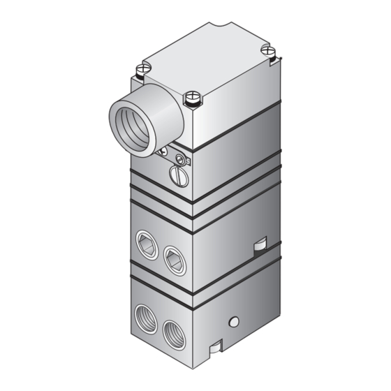
Figure 1. Model T7800 Extended Range Transducer Identification Number System.
GENERAL INFORMATION
The Model T7800 Series of Electro-Pneumatic Trans-ducer converts
a DC input signal to a linearly proportional pneumatic output pressure.
SPECIFICATIONS
FAIRCHILD T7800 EXTENDED RANGE
Functional Specifications
psig
[BAR]
(kPa)
0-30
Output
[0-2.0]
Range
(0-200)
Input
Range
35-150
1
Supply
[2.5-10]
Pressure
(250-1000)
12.5
Minimum
[0.85]
Span
(85)
1
Supply Pressure must be no less than 5 psig, [0.35 BAR],
(35 kPa) above maximum output.
0 psig
Air Con-
[0 BAR]
sumption
(0 kPa)
0- 30 psig
3.1
(.09 m /HR)
SCFH
3
0- 60 psig
1.6
(.04 m /HR)
3
SCFH
0.5
0-120 psig
(.01 m /HR)
3
SCFH
Flow Rate
11.0 (18.7m /HR) @150 psig, [10 BAR],
S C F M
(1000 kPa) supply & midscale output.
Temper-
Operating . . . . . . . . . . . . . . . . . . . . .
a t u r e
Range
Storage . . . . . . . . . . . . . . . . . . . . .
Span/Zero
Adjustments
Required
Two Wire Current Input
Operating
Voltages
Supply
Three Wire Voltage Input
Voltage
S i g n a l
Three Wire Voltage Input
Impedance
1
psig
psig
[BAR]
[BAR]
(kPa)
(kPa)
0-60
0-120
[0-4.0]
[0-8.0]
(0-400)
(0-800)
4-20 mA DC, 0-10 VDC,
1-9 VDC, 0-5 VDC, 1-5 VDC
65-150
125-150
[4.6-10]
[8.8-10]
(460-1000)
(880-1000)
25
50
[1.5]
[3.0]
(150)
(300)
Set Point
15 psig
120 psig
30 psig
60 psig
[8.0 BAR]
[1.0 BAR]
[2.0 BAR]
[4.0 BAR]
(800 kPa)
(100 kPa)
(400 kPa)
(200 kPa)
7.81
11.8
(.22 m /HR)
3
(.33 m /HR)
3
4.7
13.3
7.8
(.13 m /HR)
3
(.22 m /HR)
(.37 m /HR)
15.1
3
3
3.8
7.6
(.42 m /HR)
(.11 m /HR)
(.21 m /HR)
3
3
3
-40 F to +160 F (-40 C to +71.2 C)
-40 F to +180 F (-40 C to +82.2 C)
Screwdriver adjustments located
on front of unit.
7.2 VDC @ 20 mA (4-20 mA signal)
7-30 VDC, less than 3 mA
10 Kilohms
3
Advertisement
Table of Contents

Related Manuals for Fairchild T7800


Summary of Contents for Fairchild T7800
-
Page 1: General Information
FAIRCHILD T7800 EXTENDED RANGE MINIATURE ELECTRO-PNEUMATIC TRANSDUCER Installation, Operation and Maintenance Instructions Figure 1. Model T7800 Extended Range Transducer Identification Number System. GENERAL INFORMATION The Model T7800 Series of Electro-Pneumatic Trans-ducer converts a DC input signal to a linearly proportional pneumatic output pressure. -
Page 2: Installation
INSTALLATION NOTE: The Model T7800 can be mounted directly onto a flat surface Part of the TDFI7800/TD7800 enclosure is constructed on Non-Metallic material. To Prevent the risk of electrostatic sparking, the enclosure using two 10-32 Screws. For more information, see Figure 2. - Page 3 Installation (continued) Figure 8. Optional Mounting Kit 19254-1. (Sold Separately) Pneumatic Connections NOTE: Instrument quality air, per ISA Standards S7.3- 1981, is required. Use a filter to remove dirt and Clean all pipelines to remove dirt and scale before installation. liquid in the air line ahead of the transducer for correct performance.
-
Page 4: Split Range Operation
Apply the maximum input signal and adjust the Zero turn back clockwise until oscillation is minimized. For screw for minimum output pressure. more information, see Figure 10. “T7800 Calibration Configuration” • Reverse Acting Calibration - Span Turn Damping Adjustment clockwise to increase Apply the minimum input signal and adjust the Span damping function. -
Page 5: Damping Adjustment
J7 Jumper J1 Jumper FORWARD ACTING Zero OPERATION Adjustment (Current Unit) Span Adjustment DAMPING ADJUSTMENT Decrease Increase Damping Damping Function Function FORWARD ACTING OPERATION (Voltage Unit) REVERSE ACTING OPERATION (Current Unit) REVERSE ACTING OPERATION (Voltage Unit) Figure 10. T7800 Calibration Configuration. - Page 6 Table 5. T7800 Transducer Components. Item Qty. Description Cover, Machining Screw Screw Gasket Nozzle Body Assembly Orifice Assembly Orifice Assembly Orifice Assembly Spring Disk Diaphragm Spacer Ring Diaphragm Assembly Foam Block Valve Body Assembly Screw Pintle Spring, PIntle O-Ring Plug...
-
Page 7: Maintenance
TROUBLE-SHOOTING MAINTENANCE Table 6. Trouble-Shooting. To clean the Orifice, use the following procedure: Problem Solution (check) Shut off the valve that is supplying air to transducer. It is not necessary to remove the Transducer No Output Supply Pressure from the air line. Clogged Orifice Leakage Connections... -
Page 8: Hazardous Locations
The information set forth in the foregoing Installation, Operation and Maintenance Instructions shall not be modified or amended in any respect without prior written consent of Fairchild Industrial Products Company. In addition, the information set forth herein shall be furnished with each product sold incorporating Fairchild's unit as a component thereof. -
Page 9: Allgemeine Informationen
Geräten mit 4-20 mA. Nicht zündfähig (Einteilung 2), Zulassung nur für Geräte mit FM- Spannungseingang. Abbildung 1. Modell T7800 mit Typenschlüssel - System ALLGEMEINE INFORMATIONEN Der Elektro-Pneumatik-Wandler Modell T7800 wandelt ein DC-Eingangssignal in einen linear proportionalen pneumatischen Ausgangsdruck um. Funktionsmerkmale psig psig... - Page 10 INSTALLATION HINWEIS: Das Modell T7800 kann direkt mit zwei 10-32 x 5/16“ -Schrauben auf Ein Teil des Gehäuses von TDFI7800/TD7800 ist auf nichtmetallischem Material eine flache Oberfläche montiert werden. Nähere Angaben finden Sie in gebaut. Zur Vermeidung von elektrostatischer Funkenbildung darf das Abbildung 2.
- Page 11 Installation (Fortsetzung) Konfiguration der 2" Rohrmontage wird mit dem Modell TT7800 gezeigt Zur Montage müssen 2Stück 5/16“ - 18 Gewindemuttern verwendet werden (in der 2" Rohrklammer enthalten) Montagebausatz 19254-1 enthält : Montagehalterung 2" Rohrklammer 2 Stück Schrauben 10-32 x 5/16” Abbildung 8.
- Page 12 Oszillation auf ein Minimum reduziert ist. Nähere Angaben finden Sie in Abbildung 10. “Kalibrierkonfiguration Rückwärts-Kalibrierung – Spannweite T7800”. Schließen Sie das Mindesteingangssignal an und 1. Drehen Sie den Schalter zum Einstellen der Dämpfung im stellen Sie die Spannweitenschraube auf maximalen Uhrzeigersinn, um die Dämpfungsfunktion zu erhöhen..
- Page 13 Kalibrierungen / Einstellungen (Fortsetzung) Tabelle 3. Fullrange-Betrieb Table 3. Full Range Operation. Tabelle 4. Splitrange-Betrieb Table 4. Split Range Operation. Span Span Stellung Stellung Input Ausgang Ausgang Output Eingang Input Output Eingang Spannweite Spannweite Position Position psig (kPa) psig (kPa) 0-15 0-100 0-30...
- Page 14 Modell Modell Modell Tabelle 5. Wandlerkomponenten Bauteil Anzahl Beschreibung Abdeckung, Verarbeitung Schraube Schraube Dichtung Düsenkorpusbaugruppe Düsenbaugruppe Düsenbaugruppe Düsenbaugruppe Feder Scheibe Membran Abstandshalter Membranbaugruppe Schaumblock Ventilkorpusbaugruppe Schraube Drehbolzen Feder, Drehbolzen O-Ring Stecker Schraube Membran Abstandshalter Membranbaugruppe Membranbaugruppe Feder Schaumblock Ventilkorpusbaugruppe Schraube Drehbolzen Feder, Drehbolzen O-Ring...
-
Page 15: Wartung
WARTUNG FEHLERDIAGNOSE Die Düse muss folgendermaßen gereinigt werden: Tabelle 6. Fehlerdiagnose. 1. Schließen Sie das Ventil, das den Wandler mit Luft versorgt. Problem Lösung (Überprüfung) Der Wandler muss nicht von der Luftzufuhrleitung Keine Ausgangsleistung Versorgungsdruck getrennt werden. Verstopfte Düse Undichtigkeit Anschlüsse 2. -
Page 16: Rechtlicher Hinweis
Die im vorangehenden Installations-, Betriebs- und Wartungshandbuch dargelegten Angaben dürfen in keinerlei Hinsicht ohne die vorherige schriftliche Zustimmung der Fairchild Industrial Products Company geändert oder ergänzt werden. Außerdem müssen die hierin dargelegten Angaben zusammen mit jedem verkauften Produkt, das ein Gerät von Fairchild als Bauteil eingebaut hat, ausgehändigt werden. -
Page 17: Informazioni Generali
Approvazione non-incendive (Divisione 2) solo su unità con ingresso con tensione FM. Figura 1. Sistema di codifica trasduttore gamma estesa Modello T7800. INFORMAZIONI GENERALI Il modello T7800 della serie di trasduttori elettropneumatico converte un segnale in ingresso DC in uscita pneumatica linearmente proporzionale. Specifiche funzionali psig... -
Page 18: Installazione
TR. Fisicamente, è uguale all’unità TT7800 (Morsettiera), Il modello T7800 è dotato di un Kit di montaggio 16799-1 per il montaggio ma la morsettiera è stata ruotata sul retro. Per ulteriori informazioni, vedere la su parete o su pannello e un Kit staffa di montaggio per montaggio 16893 su binario DIN. - Page 19 Installazione (segue) Configurazione di montaggio della tubazione da 2 pollici mostrata con il modello TT7800 Usare due dadi filettati per il montaggio (inclusi con morsetto per tubi da 2 pollici) Kit di montaggio 19254-1 include quanto segue: Staffa di montaggio Morsetto per tubazione da 2”...
- Page 20 Per ulteriori informazioni, vedere la Figura 10. “Configurazione della Taratura azionamento indietro – Span taratura T7800” Applicare il segnale di ingresso minimo e regolare la vite 1. Ruotare verso destra la regolazione di smorzamento per Span per la pressione di uscita massima.
- Page 21 FUNZIONAMENTO FORWARD ACTING INDIETRO OPERATION (Voltage Unit) REVERSE ACTING (Unità tensione) FUNZIONAMENTO INDIETRO OPERATION (Unità corrente) (Current Unit) FUNCIONAMIENTO REVERSE ACTING EN MODO INVERSO OPERATION (Voltage Unit) (unidad con señal de tensión) Figura 10. T7800 Configurazione della taratura...
- Page 22 Modello Modello Modello Tabella 5. Componenti del trasduttore Articolo Quantità Descrizione Coperchio, lavorazione meccanica Vite Vite Guarnizione Gruppo corpo ugello Gruppo orifizio Gruppo orifizio Gruppo orifizio Molla Disco Diaframma Anello distanziatore Gruppo diaframma Blocco in schiuma Gruppo corpo valvola Vite Cardine Molla, Cardine O-Ring...
-
Page 23: Manutenzione
RISOLUZIONE DEI PROBLEMI MANUTENZIONE Per pulire l’orifizio, attenersi alla seguente procedura: Tabella 6. Risoluzione dei problemi 1. Spegnere la valvola che alimenta l’aria verso il trasduttore. Problema Soluzione (controllare) Non è necessario rimuovere il trasduttore dalla linea Nessuna uscita Pressione di alimentazione dell’aria. - Page 24 Le informazioni indicate nelle precedenti istruzioni sull’installazione, uso e manutenzione non possono essere modificate o corrette in alcun modo senza previo consenso scritto da parte di Fairchild Industrial Products Company. Inoltre, tali informazioni devono essere fornite insieme a ogni prodotto venduto di cui l’unità Fairchild è componente.
-
Page 25: Spécifications
FM uniquement. Figure 1. Modèle de transmetteur gamme étendue T7800 avec système de numéros d’identification Informations générales Le modèle de transmetteur électropneumatique T7800 convertit un signal d’entrée CC en une pression de sortie pneumatique linéairement proportionnelle. Spécifications fonctionnelles psig psig psig SPÉCIFICATIONS... - Page 26 TR. Physiquement, il s’agit du Le modèle T7800 est fourni avec un kit de montage 16799-1 pour un même modèle que l’unité TT7800 (bornier), excepté que le bornier a été pivoté à...
- Page 27 Installation (suite) Configuration de montage sur un tuyau 2” présentée avec le modèle TT7800 Utilisez deux 5/16"-18 écrous filetés pour le montage (inclus avec le collier de serrage pour tuyau 2”) Le kit de montage 19254-1 inclut les éléments suivants: Support de montage Collier de serrage pour tuyau 2”...
- Page 28 Pour plus d’informations, voir la figure 10. « Configuration Appliquez le signal d’entrée minimal et réglez la vis de d’étalonnage T7800 » réglage de l’étendue d’échelle pour la pression de sortie maximale.
- Page 29 FORWARD ACTING DE L’ACTION AVANCÉE OPERATION FONCTIONNEMNT (Voltage Unit) REVERSE ACTING (Unité de tension) DE L’ACTION INVERSÉE OPERATION (Current Unit) (Unité de courant) FONCTIONNEMNT REVERSE ACTING DE L’ACTION INVERSÉE OPERATION (Voltage Unit) (Unité de tension) Figure 10. T7800 Configuration d’étalonnage...
- Page 30 Modèle Modèle Modèle Tableau 5. Composants du transmetteur Élément Quantité Description Couverture, Usinage Joint d’étanchéité Assemblage du corps de la buse Assemblage de l’orifice Assemblage de l’orifice Assemblage de l’orifice Ressort Disque Diaphragme Bague d’écartement Assemblage du diaphragme Bloc de mousse Assemblage du corps de la vanne Cheville Ressort, Cheville...
- Page 31 DÉTECTION DES PANNES MAINTENANCE Pour nettoyer l’orifice, utilisez la procédure suivante: Tableau 6. Détection des pannes. 1. Fermez la vanne qui alimente le transmetteur en air. Problème Solution (contrôle) Il n’est pas nécessaire de retirer le transmetteur du Aucune sortie Pression d’alimentation conduit d’air.
-
Page 32: Zones Dangereuses
Les informations figurant dans ces instructions d’installation, de fonctionnement et de maintenance ne doivent en aucun cas être modifiées ni amendées, sans l’autorisation écrite préalable de la société de produits industriels Fairchild. De plus, les informations incluses dans ce document doivent être fournies avec chaque produit vendu incorporant l’unité Fairchild. -
Page 33: Información General
FM con entrada de tensión. Figura 1. Sistema de referencias de identificación de los transductores T7800 (gama ampliada). INFORMACIÓN GENERAL Los transductores electro neumáticos T7800 transforman una señal de entrada de CC en una salida de presión neumática directamente proporcional. Especificaciones funcionales psig... -
Page 34: Instalación
El transductor TR7800 está diseñado para ser utilizado con el kit de bastidor El Modelo T7800 es suministrado con un kit de montaje 16799 para TR. Físicamente es idéntico al del transductor TT7800, con la salvedad de que realizar su montaje en panel o en pared y un kit de montaje 16893 para carril DIN. - Page 35 Instalación (continuación) Configuración de montaje en tubería de 2" mostrada para el transductor Utilice dos 5/16"-18 tuercas para el montaje (incluidas con la abrazadera para tubería de 2") El kit de montaje 19254-1 incluye los siguientes elementos: Soporte de montaje Abrazadera para tubería de 2"...
- Page 36 Calibración de la amplitud en el modo inverso oscilación. Para obtener más información, consulte la figura 10, “Configuración de calibración de los transductores T7800”. Aplique la señal de entrada mínima y ajuste el tornillo de la amplitud para obtener la presión de salida máxima.
- Page 37 Calibraciones y ajustes (continuación) Table 3. Full Range Operation. Tabla 3. Funcionamiento con rango completo Table 4. Split Range Operation. Tabla 4. Funcionamiento con rango dividido Posición Span Span Posición Input Output Entrada Salida Input Output Entrada Salida Position Position de amplitud de amplitud psig...
- Page 38 Modelo Modelo Modelo Tabla 5. Componentes de los transductores Ref. Cant. Descripción Cubierta, Mecanizado Tornillo Tornillo Junta Conjunto de cuerpo de boquilla Conjunto de orificio Conjunto de orificio Conjunto de orificio Muelle Disco Diafragma Anillo separador Conjunto de diafragma Bloque de espuma Conjunto de cuerpo de válvula Tornillo Pivote...
-
Page 39: Mantenimiento
RESOLUCIÓN DE PROBLEMAS MANTENIMIENTO Para limpiar el orificio, siga el procedimiento indicado Tabla 6. Resolución de problemas. a continuación: Problema Solución (elementos a comprobar) 1. Cierre la válvula de suministro de aire al transductor. No Ausencia de salida Presión de suministro es necesario desmontar el transductor de la tubería Orificio obstruido de aire. -
Page 40: Áreas Peligrosas
La información contenida en las presentes instrucciones de instalación, uso y mantenimiento no debe modificarse ni alterarse de ningún modo sin el consentimiento previo por escrito de Fairchild Industrial Products Company. Asimismo, la información incluida en el presente documento debe entregarse junto con todos y cada uno de los productos comercializados que incorporen unidades de Fairchild como componentes.
Need help?
Do you have a question about the T7800 and is the answer not in the manual?
Questions and answers