Table of Contents
Advertisement
Quick Links
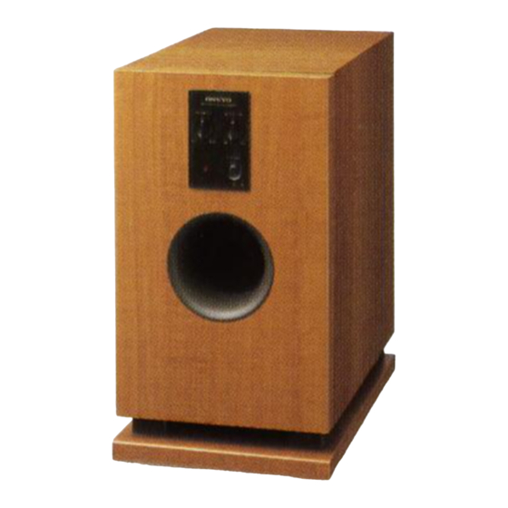
POWERED SUBWOOFER
Black color : MPP model
Yellow color : MDT, MGT models
SERVICE MANUAL
SERVICE MANUAL
SUB WOOFER SYSTEM
SL-105 / HTP-2
SL-105
MPP
230-240V AC, 50Hz
MDT
120V AC, 60Hz
MGT
220-230V AC, 50/60Hz
SAFETY-RELATED COMPONENT
WARNING!!
COMPONENTS IDENTIFIED BY MARK
SCHEMATIC DIAGRAM AND IN THE PARTS LIST ARE
CRITICAL FOR RISK OF FIRE AND ELECTRIC SHOCK.
REPLACE THESE COMPONENTS WITH ONKYO
PARTS WHOSE PART NUMBERS APPEAR AS SHOWN
IN THIS MANUAL.
MAKE LEAKAGE-CURRENT OR RESISTANCE
MEASUREMENTS TO DETERMINE THAT EXPOSED
PARTS ARE ACCEPTABLY INSULATED FROM THE
SUPPLY CIRCUIT BEFORE RETURNING THE
APPLIANCE TO THE CUSTOMER.
D-L5 x 5
SATELLITE SPEAKERS
ON THE
SL-105
Ref. No.3709
082001
Advertisement
Table of Contents


Need help?
Do you have a question about the SL-105 and is the answer not in the manual?
Questions and answers