Table of Contents
Advertisement
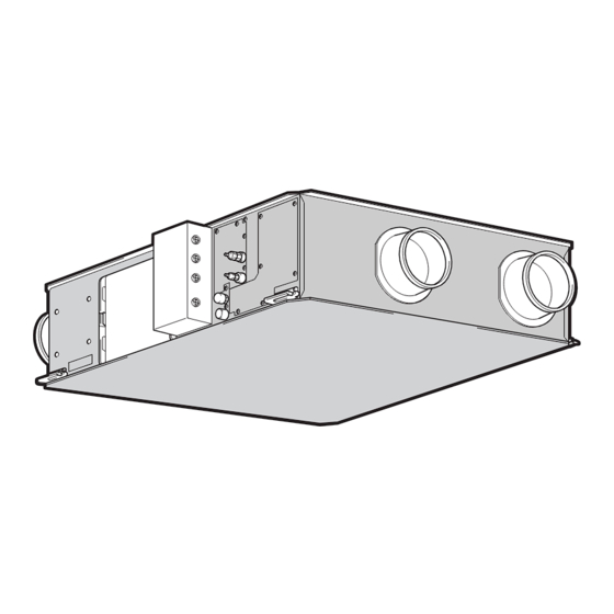
Fresh Master
Models:
GUF-50RDH3
GUF-100RDH3
Installation Instructions
(For use by dealer/contractor)
GUF-50RDH3 shown above.
Humidifier function not available on GUF-50RD3 and
GUF-100RD3.
GUF-50RD3
•
GUF-100RD3
•
Contents
1. Safety precautions ............................................ 2-4
2. Accessories .......................................................... 5
3. Outline drawings .................................................. 5
4. Selecting an installation site ................................. 6
5. Installing the Fresh Master ................................ 6-7
6. Supply pipe and drain pipe work .......................... 8
7. Refrigerant pipe work ...................................... 9-11
8. Electrical wiring ............................................. 12-16
9. Feature settings ............................................ 17-19
10. Test run ......................................................... 19-20
11. Troubleshooting ................................................. 21
• Please take the time to read through these instruc-
tions before commencing with the installation work.
They will help to install the Fresh Master properly and
safely.
• The separate Operating Instructions are for the user.
Make sure that they are handed over to the customer.
The warranty will not apply to damage resulting
from failure to follow the warnings and precau-
tions set forth in the Installation Instructions.
For use with the R410A&R407C&R22
Advertisement
Table of Contents

Related Manuals for Mitsubishi Electric Fresh Master GUF-50RD3


Summary of Contents for Mitsubishi Electric Fresh Master GUF-50RD3
-
Page 1: Table Of Contents
Fresh Master Models: GUF-50RDH3 GUF-50RD3 • GUF-100RDH3 GUF-100RD3 • Installation Instructions (For use by dealer/contractor) Contents 1. Safety precautions ..........2-4 2. Accessories ............5 3. Outline drawings ..........5 4. Selecting an installation site ......... 6 5. Installing the Fresh Master ........ 6-7 6. -
Page 2: Safety Precautions
If the unit is installed improperly, water leakage, electric shock or fire may result. • Use only accessories authorized by Mitsubishi Electric and ask your dealer or an authorized company to install them. If accessories are installed improperly, water leakage, electric shock or fire may result. -
Page 3: R410A Refrigerant
1.2. Precautions for devices that use ø6.35, Wall thickness 0.8 mm ø9.52, Wall thickness 0.8 mm R407C refrigerant ø12.7, Wall thickness 0.8 mm ø15.88, Wall thickness 1.0 mm It is strictly prohibited to use pipes with thin wall not listed in Caution: the above table. -
Page 4: Before Getting Installed
1.5. Before getting installed 1.7. Before starting the test run Caution: Caution: • Turn on the power at least 12 hours before starting operation. • Do not install the unit where combustible gas may leak. - If the gas leaks and accumulates around the unit, an explosion - Starting operation immediately after turning on the main power may result. -
Page 5: Accessories
2. Accessories The unit is provided with the following accessories: Accessories Pipe insulation Flare insulation Tie band Duct connecting flanges Mounting screws 3. Outline drawings Location at which the duct direction can be changed Damper plate Ceiling suspension fixture (4-13×30 length hole for GUF-50RDH3 · 50RD3) Ceiling suspension fixture (4-15×30 length hole for GUF-100RDH3 ·... -
Page 6: Selecting An Installation Site
4. Selecting an installation site • Select a site with sturdy fixed surface sufficiently durable against 4.1. Install the Fresh Master on a ceiling the weight of unit. strong enough to sustain its weight • Before installing unit, the route to carry the unit to the installation site should be determined. -
Page 7: Hanging The Unit Body
5.2. Attaching the duct connecting Mounting the duct connection flange 1. Use the mounting screws provided to mount the duct connection flanges flange to the main body. 2. Use the four mounting screws that were removed to attach the Use the screws supplied to secure the duct connecting flanges to the flange cover. -
Page 8: Supply Pipe And Drain Pipe Work
6. Supply pipe and drain pipe work Supply pipe work is not required for GUF-50 100RD3. Only perform 6.2. Drain pipe work • the drain pipe work. 1. Connect a vinyl chloride VP25 elbow to the drain discharge port. 6.1. Supply pipe work 2. -
Page 9: Refrigerant Pipe Work
7. Refrigerant pipe work 7.1. Refrigerant pipe specifications 7.2. Refrigerant piping work To avoid dew drops, provide sufficient insulation to the refrigerant and This piping work must be done in accordance with the installation manu- drain pipes. als for both outdoor unit and BC controller (simultaneous cooling and When using commercially available refrigerant pipes, be sure to use heating series R2). - Page 10 • Make sure to use new refrigerant piping. Coat small amount of ester oil, ether oil or hard alkylbenzen oil over - When using the existing piping which used R22, take care of the the entire periphery of flare seat surface. following points.
- Page 11 7.3. Request for refrigerant piping connection Description of parts to be used Work procedures Detail of work Item to be observed Reference drawing Mount the provided “IN” and “OUT” are marked on the • Using the flare insulation of a different type Fig-1 pipe insulation (1) on inside of the flare insulation.
-
Page 12: Electrical Wiring
8. Electrical wiring 5. Some cables (power, Remote controller, transmission cables) above 8.1. Precautions on electrical wiring the ceiling may be bitten by mice. Use as many metal pipes as possible to insert the cables into them for protection. Warning: 6. -
Page 13: Electrical Wiring
GUF50-100RDH3 8.3. Electrical wiring diagram I GUF-50 100RDH3 • • TM1, TM2, TM3 shown in dotted lines are field work. • Be sure to connect the grounding wire. • Breakers and controller switches should be provided by the customer. GREEN/YELLOW POWER SUPPLY BROWN BROWN... - Page 14 I GUF-50 100RD3 • • TM1, TM2, TM3 shown in dotted lines are field work. • Be sure to connect the grounding wire. • Breakers and controller switches should be provided by the customer. GREEN/YELLOW POWER SUPPLY BROWN BROWN BLUE 220-240V ~ 50Hz CND1 WHITE...
-
Page 15: Power Supply Wiring
8.4. Power supply wiring • 24 to 30 V DC between M1 and M2 Longest wiring length (L1+L2+L4 or L1+L3): less than 200 m Power cable size: 1.5 mm or more Longest wiring length (L2+L3+L4): less than 500 m Total operating current Over current Length between the Fresh Master and the Remote controller (R): within be less than 16 A... -
Page 16: Connecting Electrical Connections
8.6. Connecting electrical connections 3. Connect the transmission line to the TM2 terminal block as shown in the diagram. 1. Remove the 4 screws to remove the control box cover. Humidistat cable PVC insulated PVC jacketed control cable 0.75 PG connection . -
Page 17: Feature Settings
9. Feature settings Caution: SW3 ---- GUF-50 100RDH3 • Always turn off the main power supply. Remove the control box cover. Synchronous air-conditioning switch (async when 9.1. Address setting Humidifier mode (OFF: humidifier; ON: heat save) (Determining the address depends on the own-site system. Please Heater operation during synchronous operation/ see to technical references, etc.) stop temperature switch... - Page 18 9.3.1. Filter maintenance time setting 9.3.5. Humidifier mode select (GUF-50 • 100RDH3 only) Set the filter maintenance display ON/OFF and time according to use. Setting the humidifier mode. Switch Maintenance time Filter maintenance display ON Switch Mode Standard humidifier mode* Filter maintenance display OFF* Heat save humidifier mode (see below) 1,500 hours...
-
Page 19: Test Run
9.3.9. Selecting the fan speed control method 9.3.10. Room temperature control (GUF-50 • 100RD3 only) This setting is used to select whether to operate according to the fan speed requested by the indoor unit, or to operate in high or low speed. Room temperature detected at main unit is decreased by 4°C when heating. -
Page 20: Test Run
I In case of abnormality during a test-run operation Notes: • It takes a while until warm air comes out when heating. When If the unit fails to operate normally, check the phenomena and causes cooling, make sure that the display on the remote control listed below, and correct the problem. -
Page 21: Troubleshooting
11. Troubleshooting See below for possible remedies when there is an error during test operation and [Check] followed by a 4-digit number is displayed on the remote controller. Error code Error content Cause Remedy 0900 Test run • Is the test operation SW of either the fan, •...
Need help?
Do you have a question about the Fresh Master GUF-50RD3 and is the answer not in the manual?
Questions and answers