Table of Contents
Advertisement
INSTRUCTION MANUAL
Thermocouple Thermometer
1
2
STORE
LOG
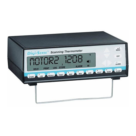
Each of the up to 12 thermocouples is scanned once every four seconds to once every
hour (settable). The current readings are displayed on the large liquid crystal display. Read-
ings that exceed a maximum or minimum value can be set to trigger an alarm.
Thermocouples of types: B, E, J, K, N, R, S or T can be used.
Up to 4,680 data points can be logged (stored) within the unit, including readings from all
12 channels and the date and time of the readings.
The unit can be directly connected to a printer to provide a continuous printout, and/or to
your computer. Software to permit a personal computer using WINDOWS
WINDOWS NT
®
to store data from the unit, remotely operate the unit, and synchronize
the operation of multiple units is included.
Digi
12-Channel Scanning
3
5
4
RECALL
MAX
PRINT
Model Nos.
69200-00 Benchtop 115V
69202-30 Benchtop 230V
Eutech Instruments Pte Ltd
Blk 55 Ayer Rajah Crescent
#04-16 Singapore 139949
Tel: (65) 6778 6876
Fax: (65) 6773 0836
Website: www.eutechinst.com
email: marketing@eutechinst.com
68X338501 Rev.0.1 02/03
Sense
–
°F
6
7
8
MIN
AVG
HOLD
®
MENU
EXIT
+-
ALARM
9
0
SCAN
CLEAR
®
95/98 or
Advertisement
Chapters
Table of Contents

Subscribe to Our Youtube Channel
Related Manuals for Digi-Sense 69202-30


Summary of Contents for Digi-Sense 69202-30
- Page 1 HOLD Model Nos. 69200-00 Benchtop 115V 69202-30 Benchtop 230V Each of the up to 12 thermocouples is scanned once every four seconds to once every hour (settable). The current readings are displayed on the large liquid crystal display. Read- ings that exceed a maximum or minimum value can be set to trigger an alarm.
- Page 2 EU Declaration of Conformity Name of Apparatus: Scanning Thermocouple Thermometer Model Number: 69202-30 Description of Apparatus: 12-Channel Benchtop Thermocouple Scanner Barnant Company declares that the above model is in conformity to the following harmonized standards and directives: Applicable Applicable Manufacturer’s...
-
Page 3: Introduction
Introduction Safety Precautions Introduction This Scanning Thermocouple Thermometer continuously monitors temperatures at up to 12 locations. It is designed for laboratory or industrial applications for unattended temperature monitoring. An alarm is set off when any thermometer exceeds its preset minimum or maximum temperature. -
Page 4: Table Of Contents
Table of Contents Page Introduction ................. Safety Precautions ..............Table of Contents ................ Features ..................Package contents ................ Quick reference: Front panel controls .............. Front panel display ............... Rear panel connections ............Rear panel connections Thermocouple connections ..........Power switch ................ 10-28V DC jack .............. -
Page 5: Table Of Contents
Table of Contents continued Page MENU - How to: Set the Scale ................ Change the resolution ............Enable/Disable channels ............Setup thermocouple types ............ Adjust the display contrast ............ Set trigger type ..............Set trigger mode ..............Adjust the scan rate .............. Adjust the print rate .............. -
Page 6: Features
Features Input • Up to 12 thermocouple probes, each connected to a separate channel. • Thermocouples can be different types. • Thermocouples of types B, E, J, K, N, R, S or T can be used. • Channels can be individually enabled or disabled. Data storage •... -
Page 7: Package Contents
Features continued Package contents Alarms • High and low alarm temperatures can be set for each channel individually. • An open thermocouple automatically triggers an alarm. • An alarm causes the alarm icon to be displayed, and emits an audible beep. -
Page 8: Quick Reference: Front Panel Controls
Quick Reference Front Panel Controls Use Left-Right arrow keys to select a channel for display. Scanning See the page number (in parenthesis) for full information about the item. stops. Push SCAN to resume. (22) Use Up-Down arrow keys to scroll thru the MENU. Otherwise inactive. (21) MENU Push to sequence through menu choices for instrument setup. -
Page 9: Front Panel Display
Quick Reference Continued Front Panel Display Rear Panel Connections °F ALARM STORE Note: Example display 1. CH and the channel number 6. Words across the bottom of the display the thermocouple that is display indicate status of the being read. instrument. -
Page 10: Rear Panel Connections Thermocouple Connections
Rear Panel Connections Thermocouple connections Power switch MODEL ####-## Mfg. By Barnant Company Barrington, IL 60010-2392 12 CHANNEL TERMOCOUPLE SCANNER PC/IN OUT/LINK TRIGGER PARALLEL PRINTER + GND 10-28 VDC 7-20 VAC 500 MA A. Thermocouple connections • Connect up to twelve thermocouples here. •... -
Page 11: 10-28V Dc Jack
Rear Panel Connections continued 10-28V DC jack PC/IN jack MODEL ####-## Mfg. By Barnant Company Barrington, IL 60010-2392 12 CHANNEL TERMOCOUPLE SCANNER PC/IN OUT/LINK TRIGGER PARALLEL PRINTER + GND 10-28 VDC 7-20 VAC 500 MA 10-28 VDC 7-20 VAC 500 MA A. -
Page 12: Out/Link Jack
Rear Panel Connections continued Out/Link jack Parallel Printer connection Trigger + Gnd connection MODEL ####-## Mfg. By Barnant Company Barrington, IL 60010-2392 12 CHANNEL TERMOCOUPLE SCANNER PC/IN OUT/LINK TRIGGER PARALLEL PRINTER + GND 10-28 VDC 7-20 VAC 500 MA A. OUT/LINK jack OUT/LINK Link connection. -
Page 13: Installation
Installation MODEL ####-## Mfg. By Barnant Company Barrington, IL 60010-2392 12 CHANNEL TERMOCOUPLE SCANNER PC/IN OUT/LINK TRIGGER PARALLEL PRINTER + GND 10-28 VDC 7-20 VAC 500 MA 1. Attach up to 12 thermocouples. 2. Connect the AC adapter to the instrument. 3. -
Page 14: Front Panel Displays And Controls
Front panel displays and controls 1 STORE button M E N U ° F E X I T A L A R M S T O R E L O G R E C A L L P R I N T A V G M A X M I N... -
Page 15: Log Button
Front panel displays and controls continued 2 LOG button M E N U ° F E X I T A L A R M S T O R E L O G R E C A L L P R I N T A V G M A X M I N... -
Page 16: Recall Button
Front panel displays and controls continued 3 RECALL button M E N U ° F E X I T A L A R M S T O R E L O G R E C A L L P R I N T A V G M A X M I N... -
Page 17: Print Button
Front panel displays and controls continued 3 RECALL button continued 4 PRINT button M E N U ° F E X I T A L A R M S T O R E L O G R E C A L L P R I N T M I N A V G... -
Page 18: Max Button
Front panel displays and controls continued 5 MAX button M E N U ° F E X I T A L A R M S T O R E L O G R E C A L L P R I N T M I N A V G M A X... -
Page 19: Min Button
Front panel displays and controls continued 6 MIN button M E N U ° F E X I T A L A R M S T O R E L O G R E C A L L P R I N T M I N A V G M A X... -
Page 20: Avg Button
Front panel displays and controls continued 7 AVG button 8 HOLD button M E N U ° F E X I T A L A R M S T O R E L O G R E C A L L P R I N T M I N A V G... -
Page 21: Scan Button
Front panel displays and controls continued 9 SCAN button 0 CLEAR button M E N U ° F E X I T A L A R M S T O R E L O G R E C A L L P R I N T M I N A V G... -
Page 22: Menu Button
Front panel displays and controls continued MENU button Up-Down Arrow keys M E N U ° F E X I T A L A R M S T O R E L O G R E C A L L P R I N T M I N A V G... -
Page 23: Left-Right Arrow Keys
Front panel displays and controls continued Left-Right Arrow keys M E N U ° F E X I T A L A R M S T O R E L O G R E C A L L P R I N T M I N A V G M A X... -
Page 24: Exit Button
Front panel displays and controls continued EXIT button ALARM button M E N U ° F E X I T A L A R M S T O R E L O G R E C A L L P R I N T M I N A V G M A X... - Page 25 Front panel displays and controls continued ALARM button continued °F ALARM STORE Temperature Alarms continued • HI temperature alarm: When a thermocouple detects a tempera- ture above the HI limit setting in the menu, ALARM is displayed, the alarm icon and the channel number 3 flash. HI will flash when that channel is displayed.
-
Page 26: Other Alarms
Front panel displays and controls continued ALARM button continued Other Alarms • OPEN thermocouple: A thermocouple channel that is OPEN (no thermocouple connected) will cause an OPEN alarm. OPEN will be displayed instead of a temperature when that channel is displayed. Check thermocouple connection, wiring to the thermocouple, or replace the thermocouple. -
Page 27: About The Menu
Front panel displays and controls continued About the MENU M E N U ° F E X I T A L A R M S T O R E L O G R E C A L L P R I N T M I N A V G M A X... - Page 28 Front panel displays and controls continued About the MENU continued About the Menu continued • Quick access - Push MENU then SCAN, PRINT, LOG, or ALARM to jump to that point in the menu. • When done with a menu setup either push EXIT to save the setup and return to scanning or push MENU to continue to the next menu setup.
-
Page 29: Set The Scale
Front panel displays and controls continued How to set the scale °F How to set the scale The instrument can record, display and print at the following scales: °F Degrees Fahrenheit °C Degrees Centigrade °R Degrees Rankin Kelvin The default scale is °F. 1, 3b M E N U °... -
Page 30: Change The Resolution
Front panel displays and controls continued How to change the resolution How to change the resolution The instrument can display and print temperatures at either 0.1° or 1° resolution. The default resolution is 0.1°. 1, 3b M E N U E X I T A L A R M S T O R E... -
Page 31: Enable/Disable Channels
Front panel displays and controls continued How to Enable/Disable channels 10 11 12 How to Enable/Disable channels A thermocouple channel can be turned off if that channel is not used or not desired. A channel that is turned off will be skipped in a scan and listed as OFF in a printout. -
Page 32: Setup Thermocouple Types
Front panel displays and controls continued How to setup thermocouple types 10 11 12 How to setup thermocouple types Thermocouples of types K, J, B, N, S, R, E or T can be used with this instrument. Any combination of thermocouple types can be used. See Appendix B for thermocouple specifications. -
Page 33: Adjust The Display Contrast
Front panel displays and controls continued How to adjust the display contrast How to adjust the display contrast The display contrast can be adjusted from 1 (very dark - the background interferes with the display) to 50 (very light - display letters and numbers are dim). -
Page 34: Set Trigger Type
Front panel displays and controls continued How to set trigger type How to set trigger type A trigger (contact between pins 1 and 2 of the trigger) can be set to: • pulse print (print one record when trigger contact is closed). •... -
Page 35: Set Trigger Mode
Front panel displays and controls continued How to set trigger mode How to set trigger mode If a trigger type is set to PRINT or STORE, the trigger mode can be set. (See How to set trigger type on preceding page.) The modes are PULSE (momentary action, as in pushing and releasing a button), and S/S (start/stop, toggle action as in switching on or off). -
Page 36: Adjust The Scan Rate
Front panel displays and controls continued How to adjust the scan rate How to adjust the scan rate The scan rate is the interval between the start of individual scans of all twelve channels. The default setting is 00:04 (4 seconds). It takes 4 seconds to do one 12 channel scan, so a scan rate of 00:04 results in continuous scanning. -
Page 37: Adjust The Print Rate
Front panel displays and controls continued How to adjust the print rate PRINT How to adjust the print rate The print rate is the time the instrument waits between printing temperature scans on the attached printer. A printer must be attached and turned on. The instrument only sends the data, there is no alarm or storage of print information if the printer is disconnected or turned off. -
Page 38: Adjust The Log Rate
Front panel displays and controls continued How to adjust the log rate How to adjust the log rate The log rate is the time the instrument waits between logging temperature scans in memory. 4,680 12 channel scans can be logged in memory, then LOG FULL is displayed. - Page 39 Front panel displays and controls continued How to adjust the log rate continued 1, 3b MENU E X I T A L A R M S T O R E L O G R E C A L L P R I N T M I N A V G M A X...
-
Page 40: Set The Alarm Mode
Front panel displays and controls continued How to set the alarm mode ALARM How to set the alarm mode The alarm mode can be ALARMS OFF, or ALARMS ON. The default setting is ALARMS OFF. In ALARMS OFF the instrument does not react to temperature extremes with an alarm. -
Page 41: Set The Alarm Print
Front panel displays and controls continued How to set the alarm print ALARM How to set the alarm print Alarm print can be PRINT ON or PRINT OFF. The default setting is PRINT ON. When set to PRINT ON a record is printed on your attached printer when an alarm event occurs. -
Page 42: Set Hi Alarm(S)
Front panel displays and controls continued How to set HI alarm(s) 11 12 ALARM OFF this setting is skipped in the MENU. The default settings are all 0’s (HI alarm off). To set HI alarm(s): 1, 4b MENU E X I T ALARM A L A R M S T O R E... -
Page 43: Set Lo Alarm(S)
Front panel displays and controls continued How to set LO alarm(s) 11 12 ALARM LO How to set LO alarm(s) The alarm mode must be ALARMS ON. If the alarm mode is ALARMS OFF this setting is skipped in the MENU. The default settings are all 0’s (LO alarm off). -
Page 44: Set Alarm Hysteresis
Front panel displays and controls continued How to set alarm hysteresis °F ALARM How to set alarm hysteresis The alarm mode must be ALARMS ON. If the alarm mode is ALARMS OFF this setting is skipped in the MENU. Note: Defaults /settings are described in ° F, the actual scale used is the scale that was previously selected. -
Page 45: Adjust Hi Alarm Setpoints
Front panel displays and controls continued How to adjust HI alarm setpoints °F ALARM How to adjust HI alarm setpoints The alarm mode must be ALARMS ON. If the alarm mode is ALARMS OFF this setting is skipped in the MENU. Only channels whose HI alarms are set to 1 (on) can have their setpoints changed. -
Page 46: Adjust Lo Alarm Setpoints
Front panel displays and controls continued How to adjust LO alarm setpoints °F ALARM How to adjust LO alarm setpoints The alarm mode must be ALARMS ON. If the alarm mode is ALARMS OFF this setting is skipped in the MENU. Only channels whose LO alarms are set to 1 (on) can have their setpoints changed. -
Page 47: Enable/Disable The Alarm Beeper
Front panel displays and controls continued How to Enable/Disable the alarm beeper How to Enable/Disable the alarm beeper Beeper on allows audible warning of alarm condition. Beeper off prevents audible warning. In either case, the icon will flash. This turns the audible beeper on or off. When off and an alarm occurs, only the flashing alarm icon is displayed. -
Page 48: Set The Date Format
Front panel displays and controls continued How to set the date format How to set the date format The date can be displayed MM/DD or DD/MM. 1, 3b MENU E X I T A L A R M S T O R E L O G R E C A L L P R I N T... -
Page 49: Set The Date
Front panel displays and controls continued How to set the date How to set the date The date can be displayed MM/DD/YY or DD/MM/YY. Check the date format (previous page) before setting the date. The internal calendar is ‘smart’. It automatically adjusts for months with 28, 30 and 31 days, and even compensates for leap year. -
Page 50: Set The Time
Front panel displays and controls continued How to set the time How to set the time The time must be set as 24-hour time. For times after 12:59 p.m. add 12 to the hours. Thus, 2:22 p.m. is 14:22, and 5:00 p.m. is 17:00. 1, 3b MENU E X I T... -
Page 51: Do A Field Calibration
Front panel displays and controls continued How to do a field calibration °F How to do a field calibration Factory calibration is stored in protected, non-volatile memory. Field calibration is usually used to reduce probe errors over a specified range. All field calibration values may be cleared (returning the instrument to factory calibration) by pushing and holding CLEAR during the power up display test. - Page 52 Front panel displays and controls continued How to do a field calibration continued 2, 5 MENU °F E X I T A L A R M S T O R E L O G R E C A L L P R I N T A V G M A X...
- Page 53 Front panel displays and controls continued How to do a field calibration continued MENU E X I T PRINT A L A R M S T O R E L O G R E C A L L P R I N T A V G M A X M I N...
-
Page 54: Print A Calibration Report
Front panel displays and controls continued How to print a calibration report Note: This is only valid if an optional parallel printer is attached to the DB-25 (M) input connection. Alternately, this report may be obtained through “ScanLink”. 1a, 3a 1c, 3b MENU E X I T... - Page 55 Front panel displays and controls continued How to print a calibration report continued To print a calibration report continued: Example field calibration report °F: Service calibration performed on 04/09/98 at 13:28:47 Field calibration status as of 04/09/98 14:12:41, scale CalPt.1 Change CalPt.2 Change...
-
Page 56: Calibration To Water
Front panel displays and controls continued How to calibrate to water How to calibrate to water Ice Point Calibrate CALPT1 to the freezing point of water (0°C or 32°F) by using crushed ice made of distilled water. Immerse the probe in a flask (insulated) filled with crushed ice and topped off with distilled water. -
Page 57: Power Up Modes
Power up modes Power up modes are special ways to clear memory or defaults during power up. To activate a power up mode: MODEL ####-## Mfg. By Barnant Company Barrington, IL 60010-2392 12 CHANNEL TERMOCOUPLE SCANNER PC/IN OUT/LINK TRIGGER PARALLEL PRINTER + GND 10-28 VDC 7-20 VAC... -
Page 58: Maintenance
Power up modes continued Maintenance Care and cleaning Push and hold: MIN & MAX to restore factory MENU defaults, or Push and hold: MENU to display the firmware version. Push EXIT or CLEAR to switch to the scanning display. Care and Cleaning Clean the case by using a mild detergent. -
Page 59: Battery
Maintenance Battery Battery A lithium battery retains the date and time when power is off or the instrument is disconnected from its power source. At room temperature and with a new battery, memory will be retained for over a year. A BAD BATTERY error message is displayed if the battery voltage is low and the battery needs replacement. -
Page 60: Warranty
WARRANTY Eutech Instruments supplies this product with a ONE-year warranty to be free from significant deviations from published specifications. If repair or adjustment is necessary within the warranty period, the problem will be corrected at no charge if it is not due to misuse or abuse on your part, as determined by Eutech Instruments. -
Page 61: Specifications
Specifications Operating Temperature (for stated accuracy) ......18°C to 28°C (64°F to 82°F) Operating Temperature (useful range)........0°C to 40°C (32°F to 104°F) Storage temperature ......–40°C to 60°C (–40°F to 110°F) Humidity (non-condensing) ....10 to 90% Altitude ..........Less than 2000 m Accuracy Thermocouple types E,J,K,N,T >–150°C ........ - Page 62 Specifications continued Typical power usage ......10–28V DC (non-polarized) Enclosure ..........molded ABS case UL-94V0 chemical resistance ......withstands standard cleaning solvents Pollution Degree ......Pollution Degree 2/ IEC664 (Indoor use—lab, office) ingress rating ........IP-32 per IEC 529 Printer connector .........
-
Page 63: Appendices A Error Messages
Appendix A Error messages Error messages are listed in alphabetical order, followed by a brief description of the error condition, followed by what action the user can take to correct the error (if possible). A/D TIMEOUT Return for service if error persists. BAD BATTERY Low battery voltage. -
Page 64: Guidelines To Thermocouple Selection
Appendix B Guidelines to Thermocouple Selection Type E Temperature range ......... -250°C to 871°C Environmental tolerance ......oxidizing, inert atmospheres. Color ............violet, + lead violet, - lead red Type J Temperature range ......... 0°C to 760°C Environmental tolerance ......vacuum, oxidizing, reducing or inert atmospheres. -
Page 65: Menu Flow Chart
Appendix D Menu flow chart Push MENU to proceed to Push MENU & left arrow key the next menu choice. to go backwards in the scale menu. °F Push EXIT to exit and Set alarm save menu changes. alarms mode Adjust resolution ALARM... -
Page 66: Calibration Report
Appendix D continued Menu flow chart Push MENU to proceed to the next menu choice. Set alarm alarms print Push MENU & left arrow key to go backwards in ALARM the menu. Set HI Push EXIT to exit and select alarms save menu changes. -
Page 67: E Factory Default Settings
Appendix E Factory Default settings A variety of parameters are user set-able using the MENU. Your menu settings are retained in memory even when the instrument is turned off or disconnected from a power source. When the unit is first turned on, the memory contains the factory default menu settings.
Need help?
Do you have a question about the 69202-30 and is the answer not in the manual?
Questions and answers