Table of Contents
Advertisement
Quick Links
Advertisement
Table of Contents

Related Manuals for Digi-Sense 92000-01


Summary of Contents for Digi-Sense 92000-01
- Page 1 99 Washington Street Melrose, MA 02176 Phone 781-665-1400 Toll Free 1-800-517-8431 Visit us at www.TestEquipmentDepot.com User Manual Digi-Sense® 12-Channel Benchtop Data Logging Thermocouple Thermometer Model: 92000-01 THE STANDARD IN PRECISION MEASUREMENT...
-
Page 2: Table Of Contents
Table of Contents Introduction ......................3 Unpacking ......................3 Initial Setup ……………………………………………………………………………...3 Thermometer Description—Front Panel .............. 4 Thermometer Description—Back Panel ............... 5 Active Display Screen ..................6 Main Menu ......................6 Global Settings ..................7-9 Channel Settings……………………………………………………………..9-13 Start/Stop Logging..…………………………………………………………….13 Copy to USB..…………………………………………………………………...13 Scan Setting…………………………………………………………….……….14 View Calibration Pts……………………………………………….……………14 DAQ Software installation………………………………………………………….15-17... -
Page 3: Introduction
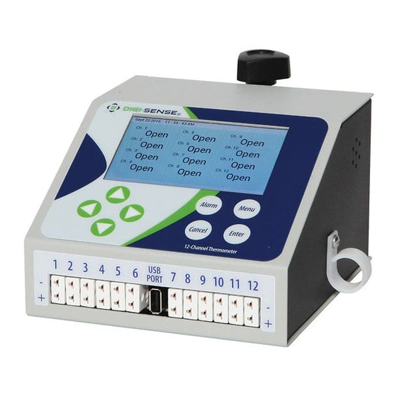
Introduction The Digi-Sense® 12-Channel Benchtop Data Logging Thermocouple Thermometer with full color LCD display. All 12 channels are easily viewed from one screen. Each channel can be configure to either J, K, T, S, R, and E type thermocouples. Alarm conditions can be configured for each channel. -
Page 4: Thermometer Description-Front Panel
Front Panel (The 12-Channel device user interface is designed to function around eight buttons, four purposed buttons and four navigation buttons.) 1. CANCEL Button For all screens where the user may change a setting on the multi- channel, pressing cancel undoes the changed setting and reverts to the previously selected option as well as clearing the confirma- tion popup. -
Page 5: Thermometer Description-Back Panel
Back Panel 1. 12 Volt DC Power input - The provided AC to DC power pack connects here. 2. Power Switch - This is used to turn the device on and off. 3. Audible Alarm Output - This output will be used to drive an outside alarm if an external alarm is required. 4. -
Page 6: Active Display Screen
Active Display Screen This is the active display screen that will be visible while navigating the menu screens. Initially, only two buttons will be active from this screen. These are the “Menu” button and the “Alarm” button. When the “Menu”... -
Page 7: Global Settings
Global Settings Global Setting includes: screen captures as the user would see of each function, description of that functions, and how to navigate through the screen in the Global Settings Menu. Global Channel: Here the user may activate/deactivate all active channels that have been enabled in the channel specific menu. - Page 8 Global Settings (Continued) Time Settings: The set time screen is where the user can set the time displayed at the top of the screen. (The user will set the hours with the Up and Down arrows. Then, the user will press the Enter button to transition to minutes.
-
Page 9: Channel Settings
Global Settings (Continued) Alarm Setpoints: Alarm Set Points for all channels can be set here. This is composed of a chosen low and high value, that will trigger the alarm. (Upon entry the high set point is un- derlined. Up and Down arrows are used to select the numeric value. - Page 10 Channel Settings (Continued) Channel Specific Menu: The Channel Specific Menu continues to display the present settings for the channel the user selected. Here the user may select what type of setting to adjust: Alarm Settings, Thermocouple Type, Calibration Settings, and Channel Enable/ Disable.
- Page 11 Channel Settings (Continued) Alarm Setpoints: Alarm Set Points are channel specific temperatures, composed of a chosen low and high value, that will trigger the alarm. (Upon entry the high set point is underlined. Up and Down arrows are used to select the numeric value.
- Page 12 Channel Settings (Continued) Calibration Settings: (Within the calibration settings menu there are four separate menu’s that are accessible; Set Calibration Points, Reset Unit Calibration, View current Calibration Points, and View Current Slopes and Offsets. The user is able to view only the last two. The other two are password protected.) Set Calibration Pts: This setting should not be changed by ...
-
Page 13: Start/Stop Logging
Channel Settings (Continued) View Current Slopes/Offsets: This function allows the user to view the slopes and offsets for each of the calibration points. A green arrow on the right queues the user to view the rest of the slopes and offsets. -
Page 14: Copy To Usb
Copy to USB Here the user will follow the on-screen instructions. No buttons will be active during this process. When finished, press the “Cancel” button to go back to the Main Menu. Make sure to stop the data log before ... -
Page 15: Daq Software Installation
Installing DAQ Software Extract the Digi_Sense.12-Channel-DAQ.Installer zip file. Run the Setup.exe file to install the software. Select the next to continue with the installation of the software. Select Cancel if you wish to abort the installation of the software. We recommend that you read the terms ... - Page 16 Select where you would like the DAQ Software to be stored on your computer. After selecting the appropriate place, click next to continue. Select Cancel if you wish to abort the installation of the software. Click Install to continue. Then wait for ...
- Page 17 Program Operations: 1. Connect the 12-Channel Benchtop Data Logging Thermocouple Thermometer to the computer with the proper USB cable. Then power on the device. This should be completed prior to start- ing the software. 2. Select the correct COM port that the computer has assigned for communications between the 12-Channel and computer.
-
Page 18: Safety
Safety Precautions DANGER: DO NOT REMOVE COVER! HIGH VOLTAGE IS PRESENT IN THE THERMOMETER. Contact supplier for service. WARNING: Specifications for the power cord: see page 19. WARNING: Use of separate temperature limit control is recommended were a fault condition could occur and result in a fire or other hazardous condition. WARNING: If Static Event occurs please power cycle the device. -
Page 19: Specifications For 12-Channel
Specifications for 12-Channel Monitoring Device Power input: 90~264VAC, 1A Operating environment: 32 to 77ºF (0 to 25ºC); 90% RH, noncondensing Maximum altitude: 2187 yd (2000 m) Pollution degree: 2 (normally only nonconductivity pollution occurs) Installation category II: local level (connect to branch circuit and not directly to a main cir- cuit, such as a fuse panel) Storage: 32 to 140ºF (0 to 60ºC);... -
Page 20: Specifications For Sensor Input
Specifications for Sensor Input Thermocouple (grounded or nongrounded) Automatic cold junction compensation and break protection for sensor Type J -310 to 1832°F (-190 to 1000°C) Type K -328 to 2502°F (-200 to 1372°C) Type T -200 to 752°F (-200 to 400°C) Type R 32 to 3214°F (0 to 1768°C) Type S... -
Page 21: Scan Rate Specifications
Scan Rate Specifications The table below shows how long the 12-Channel Benchtop Data Logging Thermocouple Ther- mometer will log data before it runs out of useable memory. The numbers below were calculated as if all 12 channels are being logged at the same time. If the user is not logging all 12 channels, they will be able to log for a longer time. -
Page 22: Screen Flow Charts
Screen Flow Charts... -
Page 23: Maintenance
Cleaning: If cleaning is necessary, use only a damp cloth with water only. Wipe only the exterior of the control chassis. CATALOG NUMBERS 92000-01 SERIAL NUMBER _______________________ DATE OF PURCHASE ___________________ 99 Washington Street...
Need help?
Do you have a question about the 92000-01 and is the answer not in the manual?
Questions and answers