Allen-Bradley SLC 500 User Manual
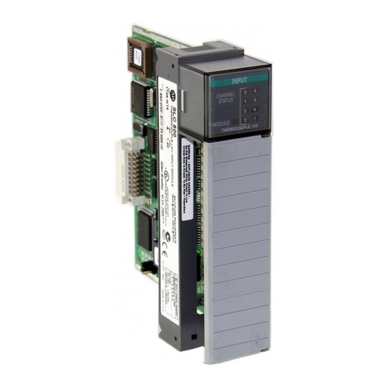
Thermocouple/mv analog input module
Hide thumbs
Also See for SLC 500:
- User manual (294 pages) ,
- Installation and operation manual (244 pages) ,
- Installation instructions manual (48 pages)

Related Manuals for Allen-Bradley SLC 500


Summary of Contents for Allen-Bradley SLC 500
- Page 1 Allen-Bradley User SLC 500™ Thermocouple/mV Manual Analog Input Module (Catalog Number 1746-NT8)
- Page 2 PLC, PLC-2, PLC-3, and PLC-5 are registered trademarks of Rockwell Automation. SLC, SLC 500, SLC 5/01, SLC 5/02, SLC 5/03, SLC 5/04, and SLC 5/05 are registered trademarks of Rockwell Automation. Belden is a trademark of Belden, Inc.
-
Page 3: Table Of Contents
Common Techniques Used in this Manual ....P-3 Allen-Bradley Support ....... P-3 Local Product Support . - Page 4 Table of Contents Things To Consider Before Using Your Module Chapter 3 Module ID Code ....... . . 3-1 Module Addressing .
- Page 5 Table of Contents Channel Filter Frequency (Bits 10 and 11) ......4-14 Open-Circuit Error (Bit 12) ....4-14 Under-Range Error (Bit 13) .
- Page 6 Table of Contents Module Specifications Appendix A Electrical Specifications ......A-1 Physical Specifications ......A-1 Environmental Specifications .
-
Page 7: Preface
Use this manual if you design, install, program, or maintain a control system that uses Allen-Bradley Small Logic Controllers (SLC). Manual You should have a basic understanding of SLC 500 products. You should also understand electronic process control and the ladder program instructions required to generate the electronic signals that control your application. -
Page 8: Related Allen-Bradley Documents
Allen-Bradley HHT (Hand-Held Terminal) User Manual 1747-NM009 Getting Started Guide for HHT (Hand-Held Terminal) SD499 Allen-Bradley Publication Index AG-7.1 Allen-Bradley Industrial Automation Glossary To obtain a copy of any of the Allen-Bradley documents listed, contact your local Allen-Bradley office or distributor. Publication 1746-6.22... -
Page 9: Common Techniques Used In This Manual
• warranty support • support service agreements Technical Product Assistance If you need to contact Allen-Bradley for technical assistance, please review the information in the Troubleshooting chapter first. Then call your local Allen-Bradley representative. Your Questions or Comments on this Manual If you find a problem with this manual, please notify us of it on the enclosed Publication Problem Report. -
Page 10: Module Overview
General Description This module is designed exclusively to mount into 1746 I/O racks for use with SLC 500 fixed and modular systems. The module stores digitally converted thermocouple/mV analog data in its image table for retrieval by all fixed and modular SLC 500 processors. The module supports connections from any combination of up to eight thermocouple/mV analog sensors. -
Page 11: Hardware Features
Hardware Features The module fits into any single slot for I/O modules in either an SLC 500 modular system or an SLC 500 fixed system expansion chassis (1746-A2), except the zero slot which is reserved for the processor. It is a Class 1 module using 8 input words and 8 output words. -
Page 12: Diagnostic Leds
Power-up and channel diagnostics are explained in Chapter 6, Testing Your Module. System Overview The module communicates with the SLC 500 processor and receives +5V dc and +24V dc power from the system power supply through the parallel backplane interface. No external power supply is required. -
Page 13: Module Operation
Module Overview After completing power-up checks, the module waits for valid channel configuration data from your SLC ladder logic program (channel status LEDs are off). After channel configuration data is transferred and channel enable bits are set, the enabled channel status LEDs turn on. -
Page 14: Block Diagram
Module Overview Block Diagram Terminal Block Module Circuitry CJCA Sensor ungrounded thermocouple Shield multiplexer User Selected Filter Frequency Within 12.5V Shield Analog to Digital Digital Digital Filter grounded Value Converter thermocouple Analog Ground Shield Shield CJCB Sensor Important: When using multiple thermocouples, the potential between any two channels cannot exceed the channel-to- channel differential voltage (12.5 volts). -
Page 15: Linear Millivolt Device Compatibility
Module Overview Linear Millivolt Device Compatibility A large number of millivolt devices may be used with the 1746-NT8 module. For this reason we do not specify compatibility with any particular device. However, millivolt applications often use strain gage bridges. A resistive voltage divider using fixed resistors is recommended for this application. -
Page 16: Installing And Wiring Your Module
Chapter Installing And Wiring Your Module Read this chapter to install and wire your module. This chapter covers: • avoiding electrostatic damage • determining power requirements • installing the module • wiring signal cables to the module’s terminal block Electrostatic Damage Electrostatic discharge can damage semiconductor devices inside this module if you touch backplane connector pins. -
Page 17: Power Requirements
0.120 0.070 Considerations for a Modular System Place your module in any slot of an SLC 500 modular, or modular expansion chassis, except for the left-most slot (slot 0) reserved for the SLC processor or adapter modules. When using the module with a modular system, add the values shown above to the requirements of all other modules in the SLC to prevent overloading the chassis power supply. -
Page 18: Fixed I/O Chassis - I/O Module Compatibility
Installing And Wiring Your Module Fixed I/O Chassis - I/O Module Compatibility The following chart depicts the range of current combinations supported by the fixed I/O expansion chassis. To use it, find the backplane current draw and operating voltage for both modules being used in the chassis. -
Page 19: General Considerations
Installing And Wiring Your Module When using the BAS or KE module to supply power to a 1747-AIC Link Coupler, the link coupler draws its power through the module. The higher current drawn by the AIC at 24V dc is shown in the table as BASn (BAS networked) and KEn (KE networked). -
Page 20: Module Installation And Removal
Apply firm even pressure on your module to attach it to its backplane connector. Never force your module into the slot. 4. Cover all unused slots with the Card Slot Filler, Allen-Bradley part number 1746-N2. Publication 1746-6.22... -
Page 21: Terminal Block Removal
Terminal Block Release Screws ATTENTION: Possible Equipment Operation Before wiring your module, always disconnect power from the SLC 500 system and from any other source to the module. Failure to observe this precaution can cause unintended equipment operation and damage. -
Page 22: Wiring Your Module
Nm (2.2 in-lb) or less, based on UL 1059, CSA C22.2 No. 158, VDE 0110B 2.79 standards. • Follow system grounding and wiring guidelines found in your SLC 500 Modular Installation and Operation Manual, publication 1747-6.2 (modular) or 1747-6.21 (fixed). Publication 1746-6.22... -
Page 23: Preparing And Wiring The Cables
Installing And Wiring Your Module Preparing and Wiring the Cables To prepare and connect cable leads and drain wires, follow these steps: Cable (Remove foil shield and drain wire from sensor end of the cable.) Signal Wires Drain Wire Signal Wires 1. - Page 24 Installing And Wiring Your Module 7. Connect TB1 chassis ground connector to the nearest chassis mounting bolt with 14 gauge wire. (Looking at the face of the module, TB1 is near the lower part of the terminal block on the primary side of the PCB.) Connect ground wire to TB1 before installing module.
-
Page 25: Cold-Junction Compensation (Cjc)
2-10 Installing And Wiring Your Module Terminal Block Diagram with Input Cable CJC A+ CJC A- Channel 0+ Thermocouple or mV Cable Channel 0- Shield for CH0 and CH1 Channel 1+ Channel 1- Channel 2+ Channel 2- Shield for CH2 and CH3 Channel 3+ Channel 3- Channel 4+... - Page 26 Installing And Wiring Your Module 2-11 To obtain accurate readings from each of the channels, the cold- junction temperature (temperature at the module’s terminal junction between the thermocouple wire and the input channel) must be compensated for. Two cold-junction compensating sensors have been integrated in the removable terminal block.
-
Page 27: Things To Consider Before Using Your Module
Chapter Things To Consider Before Using Your Module This chapter explains how the module and the SLC processor communicate through the processor’s I/O image tables. It also describes the module’s input filter characteristics. Topics discussed include: • module ID code •... -
Page 28: Module Addressing
Things To Consider Before Using Your Module Module Addressing The following memory map shows you how the SLC processor’s output and input tables are defined for the module. Image Table Bit 15 Bit 0 Address Channel 0 Configuration Word Word 0 O:e.0 Channel 1 Configuration Word Word 1... -
Page 29: Input Image - Data Words And Status Words
Things To Consider Before Using Your Module Input Image - Data Words and Status Words Eight words of the SLC processor’s input image table are reserved for the module. Input image words are multiplexed since each channel has one data word and one status word. The corresponding configuration word selects whether the channel status or channel data is in the input image word. -
Page 30: Channel Cut-Off Frequency
Things To Consider Before Using Your Module Cut-off frequency, Step Response Time, and Effective Resolution (Based on Filter Frequency) ADC Effective Filter Frequency Cut-Off Frequency Step Response Resolution 10 Hz 2.62 Hz 400 ms 20.5 50 Hz 13.1 Hz 80 ms 19.0 60 Hz 15.72 Hz... - Page 31 Things To Consider Before Using Your Module Signal Attenuation with 10 Hz Input Filter -3 dB -100 Amplitude (in dB) -120 -140 -160 -180 -200 60 Hz 2.62 Hz Signal Frequency Signal Attenuation with 50 Hz Input Filter -3 dB -100 Amplitude (in dB) -120...
-
Page 32: Channel Step Response
Things To Consider Before Using Your Module Signal Attenuation with 60 Hz Input Filter -3 dB -100 Amplitude (in dB) -120 -140 -160 -180 -200 360 Hz 15.7 Hz Signal Frequency Signal Attenuation with 250 Hz Input Filter -3 dB -100 Amplitude (in dB) -120... -
Page 33: Update Time
Things To Consider Before Using Your Module Update Time The thermocouple module update time is defined as the time required for the module to sample and convert the input signals of all enabled input channels and make the resulting data values available to the SLC processor. -
Page 34: Times
Things To Consider Before Using Your Module Using the values from the table on page 3-7, add the sum of all enabled channel sample times, plus one CJC update time. Channel 0 sampling time 66 msec Channel 1 sampling time 66 msec Channel 2 sampling time 140 msec... -
Page 35: Response To Slot Disabling
Things To Consider Before Using Your Module Response to Slot By writing to the status file in the modular SLC processor, you can disable any chassis slot. Refer to your SLC programming manual for Disabling the slot disable/enable procedure. ATTENTION: POSSIBLE EQUIPMENT OPERATION Always understand the implications of disabling a module before using the slot disable feature. -
Page 36: Channel Configuration, Data, And Status
Chapter Channel Configuration, Data, and Status Read this chapter to: • configure each input channel • check each input channel’s configuration and status Channel Configuration Channel configuration words appear in the SLC processor’s output image table as shown below. Words 0-7 correspond to module channels 0-7. -
Page 37: Channel Configuration Procedure
Channel Configuration, Data, and Status The configuration word default settings are all zero. Next, we describe how you set configuration bits of a channel configuration word to set up the following channel parameters: • data format such as engineering units, counts, or scaled for PID •... - Page 38 Channel Configuration, Data, and Status 7. Ensure that bits 12 through 14 contain zeros. 8. Determine whether the channel input image word should contain data or status. Place a one in bit 15 if channel data is desired. Place a zero in bit 15 if status is desired. 9.
- Page 39 Channel Configuration, Data, and Status A detailed explanation appears in the following table: Channel Configuration Word (O:e.0 through O:e.7) - Bit Definitions Channel Channel Disable Enable Channel Enable Thermocouple Type J Thermocouple Type K Thermocouple Type T Thermocouple TypeE Thermocouple Type R Thermocouple TypeS Thermocouple Type B Input...
-
Page 40: Select Channel Enable (Bit 0)
Channel Configuration, Data, and Status Select Channel Enable (Bit 0) Use the channel enable bit to enable a channel. The thermocouple module only scans enabled channels. To optimize module operation and minimize throughput times, unused channels should be disabled by setting the channel enable bit to zero (default value). When set (1) the channel enable bit is used by the module to read the configuration word information selected. -
Page 41: Using Scaled-For-Pid And Proportional Counts
Channel Configuration, Data, and Status Using Scaled-for-PID and Proportional Counts The thermocouple module provides eight options for displaying input channel data. These are 0.1°F, 0.1°C, 1°F, 1°C, 0.01 mV, 0.1 mV, Scaled-for-PID, and Proportional Counts. The first six options represent real Engineering Units displayed by the 1746-NT8 and do not require explanation. -
Page 42: Scaling Examples
Channel Configuration, Data, and Status Scaling Examples Scaled-for-PID to Engineering Units Equation: Engineering Units Equivalent = S + [(S ) x (Scaled-for-PID value displayed/16384)] HIGH Assume type J input type, scaled-for-PID display type, channel data = 3421. Want to calculate °C equivalent. From Channel Data Word Format table, S = -210°C and S = 760°C. - Page 43 Channel Configuration, Data, and Status 1746-NT8 Thermocouple Module - Channel Data Word Format Data Format Engineering Units x10 Engineering Units x1 Input Scaled-for- Proportional Counts Type ° Celsius ° Fahrenheit ° Celsius ° Fahrenheit -210 to +760 -346 to +1400 -2100 to +7600 -3460 to +14000 0 to +16383...
-
Page 44: Select Open-Circuit State (Bits 7 And 8)
Channel Configuration, Data, and Status 1746-NT8 Thermocouple Module - Channel Data Word Resolution Data Format Engineering Units x 10 Engineering Units x 1 Scaled-for-PID Proportional Counts Input Type ° Celsius ° Fahrenheit ° Celsius ° Fahrenheit ° Celsius ° Fahrenheit °... -
Page 45: Select Temperature Units (Bit 9)
4-10 Channel Configuration, Data, and Status Selecting maximum forces the (01) channel data word value to its full scale value during an open-circuit condition. The full scale value is determined by the selected input type and data format. Selecting minimum forces the (10) channel data word value to its low scale value during an open-circuit condition. -
Page 46: Unused Bits (Bits 12 Through 14)
Channel Configuration, Data, and Status 4-11 • 250 Hz setting provides minimal noise filtering. • 60 Hz setting provides 60 Hz AC line noise filtering. • 50 Hz setting provides 50 Hz AC line noise filtering. • 10 Hz setting provides both 50 Hz and 60 Hz AC line noise filtering. -
Page 47: Channel Data/Status Word
4-12 Channel Configuration, Data, and Status Channel Data/Status The actual thermocouple or millivolt input data values or channel status reside in I:e.0 through I:e.7 of the thermocouple module input Word image file. The data values present depend on the input type and data formats you have selected. - Page 48 Channel Configuration, Data, and Status 4-13 Channel 0-7 Status Word (I:e.0 through I:e.7) - Bit Definitions Channel Channel Disable Status Channel Enable Thermocouple Type J Thermocouple Type K Thermocouple Type T Thermocouple TypeE Thermocouple Type R Thermocouple TypeS Thermocouple Type B Thermocouple Type N Input Type...
-
Page 49: Channel Status (Bit 0)
4-14 Channel Configuration, Data, and Status Important: If the channel for which you are seeking status is disabled, all bit fields are cleared. The status word for any disabled channel is always 0000 0000 0000 0000 regardless of any previous setting that may have been made to the configuration word. -
Page 50: Under-Range Error (Bit 13)
Channel Configuration, Data, and Status 4-15 Under-Range Error (Bit 13) This bit is set (1) whenever a configured channel detects an under- range condition for the channel data. An under-range condition exists when the input value is equal to or below the specified lower limit of the particular sensor connected to that channel. -
Page 51: Basic Example
Chapter Programming Examples Earlier chapters explained how the configuration word defines the way a channel operates. This chapter shows the programming required to configure the module. It also provides you with segments of ladder logic specific to unique situations that might apply to your programming requirements. -
Page 52: Procedure
Programming Examples Procedure 1. Create integer file N10. Integer file N10 should contain eight elements (N10:0 through N10:7). 2. Using the programming software, enter the configuration parameters for all eight thermocouple channels into data file locations N10:0 through N10:7. Data table for initial programming address data address... -
Page 53: Automatic Monitoring Thermocouples And Cjc Sensors
Programming Examples Automatic Monitoring The following example explains how to change data in the channel configuration word when the channel is currently enabled. Thermocouples and CJC Sensors Example - Execute a dynamic configuration change to channel 0 of the thermocouple module located in slot 1 of a 1746 chassis. Periodically (e.g., every 60 seconds) change from monitoring an external type K thermocouple to monitoring the CJC sensors mounted on the terminal block. - Page 54 Programming Examples During the first pass, send the channel configuration data to the thermocouple module. #NT8_CONFIGURATION First Pass 0000 Copy File Source #N10:0 Dest #O:1.0 Length CHECKING_CJC B3:6 If not Checking CJC, copy Channel 0 temperature data into data location for use. Temperature control logic should use N10:20 rather than the TC input image (I:1.0) to eliminate problems during CJC checking.
- Page 55 Programming Examples Wait 7 seconds for Channel 0 to accept CJC configuration and provide a data value (time depends on module configuration). CHECKING_CJC CJC_CFG_TMR B3:6 0005 Timer On Delay Timer T11:1 Time Base Preset 7< Accum 0< Copy CJC Temperature (I:1.0) into CJC register (N10:12) CJC_CFG_TMR/DN CJC_TEMP T11:1...
- Page 56 Programming Examples Update Time Calculation Ch 0 Update Time 0.470 Ch 0 Open Circuit Check 0.045 Ch 1 Update Time 0.470 Ch 1 Open Circuit Check 0.045 Ch 2 Update Time 0.470 Ch 2 Open Circuit Check 0.045 Ch 3 Update Time 0.470 Ch 3 Open Circuit Check 0.045...
-
Page 57: Interfacing To The Pid Instruction
Programming Examples Interfacing to the PID The thermocouple module was designed to interface directly to the SLC 5/02™ or later processor PID instruction without the need for an Instruction intermediate scale operation. Example - Use 1746-NT8 channel data as the process variable in the PID instruction. -
Page 58: Monitoring Channel Status Bits
Programming Examples Monitoring Channel The following example shows how to monitor the open-circuit error bits of each channel and set an alarm in the processor if one of the Status Bits thermocouples opens. An open-circuit error can occur if the thermocouple breaks, one of the thermocouple wires gets cut or disconnected from the terminal block, or if the CJC sensors are not installed or are damaged. - Page 59 Programming Examples Monitoring Channel Status Bits Example During 1st program scan, copy thermocouple channel configuration words (N10:0 - N10:7) to NT8. In addition, initialize channel error registers (N10:20 - N10:27) and Error Flags (B3/112 - B3/119). #NT8_CH_CNF 0000 Copy File Source #N10:0 Dest...
- Page 60 5-10 Programming Examples After waiting for the NT8 to update its I/O image, check each channel’s status error bits by masking off the appropriate bits and checking if these bits are set (non-zero). If an error is detected, set the appropriate channel status error bits (B3:112 - B3/119).
- Page 61 Programming Examples 5-11 NT8_CH2_STS_FLAGS NT8_CH2_ERROR B3:7 Not Equal Source A N10:22 0< Source B 0< NT8_CH3_STS_FLAGS Masked Move Source I:1.3 0< Mask 0F000h -4096< Dest N10:23 0< NT8_CH3_STS_FLAGS NT8_CH3_ERROR B3:7 Not Equal Source A N10:23 0< Source B 0< After waiting for the NT8 to update its I/O image, check each channel’s status error bits by masking off the appropriate bits and checking if these bits are set (non-zero).
- Page 62 5-12 Programming Examples NT8_CH5_STS_FLAGS NT8_CH5_ERROR B3:7 Not Equal Source A N10:25 0< Source B 0< NT8_CH6_STS_FLAGS Masked Move Source I:1.6 0< Mask 0F000h -4096< Dest N10:26 0< NT8_CH6_STS_FLAGS NT8_CH6_ERROR B3:7 Not Equal Source A N10:26 0< Source B 0< NT8_CH7_STS_FLAGS Masked Move Source I:1.7...
-
Page 63: Plc 5 Example With Nt8 In Remote I/O Rack
1746-NT8 module in a remote rack. Note, the example provides code which will reconfigure the module if the PLC/ 5 senses are remote rack fault. Also, the PLC/5 processor uses the exact same configuration words as the SLC 500 processors. Publication 1746-6.22... - Page 64 5-14 Programming Examples During the first scan, clear the NT8 Configurated bit (B3/4) to initiate the NT8 configuration process. First scan or SFC step NT8_CONFIGURED B3:0 If the NT8 is configured and a rack fault occurs, clear the NT8 Configured bit (B3/4) to initiate the NT8 configuration process.
-
Page 65: Module And Channel Diagnostics
Chapter Troubleshooting Your Module This chapter describes troubleshooting with channel-status and module-status LEDs. It explains the types of conditions that might cause the module to flag an error and suggests what corrective action you could take. Topics include: • module and channel diagnostics •... -
Page 66: Led Indicators
The module is No action required. operating properly. The module is turned Cycle power. If the condition persists, call your off, or it detected a local Allen-Bradley distributor for assistance. module fault. Jumper may in wrong Flashing Check jumper 1position. position... -
Page 67: Channel-Status Leds (Green)
Troubleshooting Your Module Channel-status LEDs (Green) The channel-status LED operates with status bits in the channel status word to indicate the following faults detected by the module: • invalid channel configuration • an open-circuit input • out-of-range errors • selected filter frequency data acquisition or auto-calibration errors When the module detects any of the following fault conditions, it causes the channel-status LED to flash and sets the corresponding... -
Page 68: Channel Error (Bit 15)
The error codes that apply to your module include (in hexadecimal): • 50 through 5E • 71 (watchdog error) • 90 through 94 For a description of the error codes, refer to the SLC 500 Instruction Set Reference Manual, publication 1746-6.15. Publication 1746-6.22... - Page 69 CJC set (1) connections. Correct and retry. Contact your local Contact your local An open-circuit condition Contact your local Allen-Bradley Allen-Bradley is present. Check channel Allen-Bradley Bit 12 distributor distributor. and CJC wiring for open or distributor.
-
Page 70: Preventive Maintenance
To protect these Maintenance boards, install the SLC 500 system in an enclosure suitable for its operating environment. Keep the interior of the enclosure clean, and whenever possible, keep the enclosure door closed. - Page 71 Maintaining Your Module And Safety Considerations Standing Clear Of Machinery – When troubleshooting a problem with any SLC 500 system, have all personnel remain clear of machinery. The problem may be intermittent, and the machine may move unexpectedly. Have someone ready to operate an emergency stop switch.
-
Page 72: Module Specifications
Appendix Module Specifications This appendix lists the specifications for the 1746-NT8 Thermocouple/millivolt Input Module. Electrical Specifications 120 mA at 5V dc Backplane Current Consumption 70 mA at 24Vdc 2.28W maximum (0.6W at 5V dc, 1.68W at 24V Backplane Power Consumption Number of Channels 8 (backplane and channel-to-channel isolated) I/O Chassis Location... -
Page 73: Environmental Specifications
Module Specifications Environmental Specifications Operating Temperature 0°C to +60°C (+32°F to +140°F) Storage Temperature -40°C to +85°C (-40°F to +185°F) Relative Humidity 5% to 95% (without condensation) Certification UL & CUL approved Class I Division 2 Hazardous Environment Hazardous Environment Classification Groups A, B, C, D CE compliant Input Specifications... -
Page 74: Millivolt
Module Specifications The accuracies specified as follows include errors due to the cold junction compensation for thermocouples and hardware and software errors associated with the system. The hardware and software errors include calibration of the system and non-linearity of the ADC. For the sake of the calculations, the resolution of the ADC was assumed to be at least 16 bits (use of the 10 Hz, 50 Hz, and 60 Hz filter frequencies). - Page 75 Module Specifications uV Err, ±100mV Span, Prop Cts, 60 Hz, 0°C 50.00 45.00 40.00 35.00 30.00 25.00 uV Error 20.00 15.00 10.00 5.00 0.00 mV Input uV Err, ±100mV Span, Prop Cts, 60 Hz, 25°C 50.00 45.00 40.00 35.00 30.00 25.00 uV Error 20.00...
-
Page 76: Thermocouple
Module Specifications uV Err, ±100mV Span, Prop Cts, 60 Hz, 60°C 90.00 80.00 70.00 60.00 50.00 uV Error 40.00 30.00 20.00 10.00 0.00 mV Input Thermocouple The following table provides the total error expected of the thermocouple based on the thermocouple type, and the given reference point, at 25°C. - Page 77 Module Specifications The following table provides the total error expected over the temperature range of the module (0 to 60°C) for each thermocouple based upon the type, and the given reference point, at the extremes of the temperature range (0 or 60°C). The calculations are based on maximum hardware/software error and maximum CJC inaccuracy over temperature.
- Page 78 Module Specifications Thermocouple J Deviations Over Temp Channel Delta Degrees C TC Input Thermocouple K Deviations Over Temp Channel Delta Degrees C TC Input Publication 1746-6.22...
- Page 79 Module Specifications Thermocouple T Deviations Over Temp Channel Delta Degrees C TC Input Thermocouple E Deviations Over Temp Channel Delta Degrees C TC Input Publication 1746-6.22...
- Page 80 Module Specifications Thermocouple R Deviations Over Temp Channel Delta Degrees C TC Input Thermocouple S Deviations Over Temp Channel Data Degrees C TC Input Publication 1746-6.22...
- Page 81 A-10 Module Specifications Thermocouple B Deviations Over Temp Channel Delta Degrees C TC Input Thermocouple N Deviations Over Temp Channel Delta Degrees C TC Input Publication 1746-6.22...
-
Page 82: Using Grounded Junction, Ungrounded Junction, And Exposed Junction Thermocouples
Appendix Using Grounded Junction, Ungrounded Junction, and Exposed Junction Thermocouples This appendix describes the types of thermocouples available and explains the trade-offs in using them with the 1746-NT8 module. Thermocouple There are three (3) types of thermocouple junctions: Types • Grounded Junction - The measuring junction is physically connected to the protective sheath forming a completely sealed integral junction. -
Page 83: Ungrounded (Insulated) Junction
Using Grounded Junction, Ungrounded Junction, and Exposed Junction Thermocouples The following illustrations show each of the three (3) thermocouple types. Grounded Junction Measuring Junction is Metal Sheath connected to sheath Extension Wire Ungrounded (Insulated) Junction Measuring Junction is isolated from sheath Exposed Junction Measuring Junction has no sheath... -
Page 84: Grounded Junction Thermocouples
Using Grounded Junction, Ungrounded Junction, and Exposed Junction Thermocouples Grounded Junction Thermocouples As shown in the following illustration on page B-3, the shield input terminals are internally connected together, which are then connected to chassis ground. Using grounded junction thermocouples with electrically conductive sheaths removes the thermocouple signal to chassis ground isolation of the module. -
Page 85: Exposed Junction Thermocouples
Using Grounded Junction, Ungrounded Junction, and Exposed Junction Thermocouples Exposed Junction Thermocouples Recommended wiring for exposed junction thermocouples is shown in the following illustration. Using exposed junction thermocouples may result in removal of channel-to-channel isolation. This may occur if multiple exposed thermocouples are in direct contact with electrically conductive process material. - Page 86 Glossary You should understand the following terms and abbreviations before using this guide. A/D – Refers to analog-to-digital conversion. The conversion produces a digital value whose magnitude is proportional to the instantaneous magnitude of an analog input signal. Attenuation – The reduction in magnitude of a signal as it passes through a system.
- Page 87 Glossary Digital filter – A low-pass filter of the A/D converter. The digital filter provides high-frequency noise rejection. Effective resolution – The number of bits in the channel data word that do not vary due to noise. Full-scale error (gain error) – The difference in slope between the actual and ideal analog transfer functions.
- Page 88 Glossary G-3 Status word – Contains status information about the channel’s current configuration and operational state. You can use this information in your ladder program to determine whether the channel data word is valid. Step response time – The time required for the A/D signal to reach 95% of its expected, final value, given a full-scale step change in the input signal.
- Page 89 Index Detection open-circuit 6-3 Addressing 3-2, 3-4, 3-6, 3-7, 3-9, 4-5, 4-6, 4-9, 4-10, 4-14, 4-15 determining 2-1 Allen-Bradley P-3 determining power requirements 2- contacting for assistance P-3 Diagnostic Analog-to-digital conversion G-1 information 6-4 Attenuation G-1 LEDs 1-3 Avoiding electrostatic damage 2-1...
- Page 90 4-10 units field 4-14 Open-circuit bit field 4-9, 4-14 Terminal block removal 2-6 condition 4-9, 4-10 Troubleshooting 6-1, 6-2, 6-5 detection 1-4, 6-3 contacting Allen-Bradley P-3 error 4-14 error bits 5-8 Out-of-range Under-range condition 4-15 condition 1-4 Over-range...
- Page 91 Back Cover Publication 1746-6.22 - July 1999 xxxxxxx-xx © 1999 Rockwell International Corporation. All rights reserved. Printed in the U.S.A.
Need help?
Do you have a question about the SLC 500 and is the answer not in the manual?
Questions and answers