Table of Contents
Advertisement
Quick Links
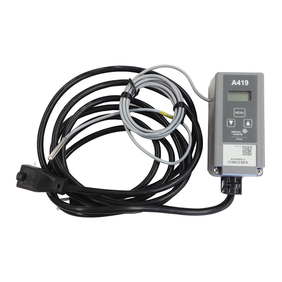
A419ABG-3C Electronic Temperature Control
Application
IMPORTANT: Use this A419ABG-3C Electronic
Temperature Control only as an operating control.
Where failure or malfunction of the A419ABG-3C
Electronic Temperature Control could lead to
personal injury or property damage to the controlled
equipment or other property, additional precautions
must be designed into the system. Incorporate and
maintain other devices such as supervisory or alarm
systems or safety or limit controls intended to warn
of, or protect against, failure or malfunction of the
A419ABG-3C Electronic Temperature Control.
The A419 Electronic Temperature Control is a
single-stage, electronic temperature control. Pre-wired
cords with plug and receptacle ends are provided for
quick and simple installation.
The control features a lockable, three-button touchpad
for setup and adjustment and a Liquid Crystal Display
(LCD) which displays the sensed temperature and
other control functions. A front panel Light-Emitting
Diode (LED) indicates the output relay status. The
control has a setpoint range of -30 to 212°F
(-34 to 100°C) and is available in 120 VAC models.
See the Technical Specifications section.
The A419 control has heating and cooling modes with
adjustable setpoint and differential, an adjustable
anti-short cycle delay, and a temperature offset
(setback) function. The control provides remote
sensing capability, and electronic accuracy in a
Type NEMA 1 high-impact plastic enclosure suitable
for surface or DIN rail mounting. The temperature
sensor supplied with the control is interchangeable
with compatible Johnson Controls/PENN® A99
temperature sensors.
© 2003 Johnson Controls, Inc.
Part No. 24-7664-2543, Rev. —
Installation Instructions
FCC Compliance
This equipment has been tested and found to comply
with the limits for a Class A digital device pursuant to
Part 15 of the FCC Rules. These limits are designed to
provide reasonable protection against harmful
interference when the equipment is operated in a
commercial environment. This equipment generates,
uses, and can radiate radio frequency energy and, if
not installed and used in accordance with the
instruction manual, may cause harmful interference to
radio communications. Operation of this equipment in
a residential area is likely to cause harmful
interference, in which case the user will be required to
correct the interference at his/her own expense.
Canadian DOC Compliance
This digital apparatus does not exceed the Class A
limits for radio noise emissions from digital apparatus
set out in the Radio Interference Regulations of the
Canadian Department of Communications.
Installation
Refer to the following guidelines, procedures and
illustrations when installing an A419 control.
Parts Included
Pre-wired cords with plug and receptacle ends are
provided for quick and simple installation.
Each A419 control includes a Johnson Controls/PENN
A99 temperature sensor. The sensor may be removed
and replaced with any compatible Johnson Controls®
A99 temperature sensor, or the wire leads on the
sensor may be extended.
See the Mounting and Wiring sections for additional
guidelines and restrictions when mounting and wiring
the control.
Issue Date June 16, 2003
www.johnsoncontrols.com
1
Advertisement
Table of Contents

Related Manuals for Johnson Controls A419ABG-3C


Summary of Contents for Johnson Controls A419ABG-3C
- Page 1 Class A digital device pursuant to Temperature Control only as an operating control. Part 15 of the FCC Rules. These limits are designed to Where failure or malfunction of the A419ABG-3C provide reasonable protection against harmful Electronic Temperature Control could lead to...
- Page 2 Dimensions 2-3/8 2-3/8 9/64 • A99 temperature sensors are not polarity (61) (61) (3.7) sensitive. Wire the leads to (+) SEN and (-) COM on the sensor terminal block (TB3). See Figure 2. Keep the leads between the control and sensor as (13) short as possible/practical in your application.
- Page 3 Used Used Male Female Plug Receptacle Figure 3: Factory Power Wiring Setup and Adjustments IMPORTANT: The touchpad cannot be unlocked without a jumper installed across the WARNING: Risk of Electrical Shock P5 jumper pins. Do not discard jumpers in case they Disconnect each of multiple power supplies before are required in the future.
- Page 4 The A419 Control Functions To position a jumper in the Installed position, place Setpoint (SP) establishes the temperature value at the jumper on both pins, which closes the circuit which the equipment is switched on or off, depending between the pins. To position a jumper in the on the user selected mode of operation.
- Page 5 Temperature Offset (OFS) establishes a set If no setup entry is made for 30 seconds, the control secondary Setpoint and Differential values that may reverts to the (normal) temperature display. be invoked to control an application when a circuit is closed between the binary input (BIN) and common IMPORTANT: If MENU is not pressed after (COM) terminals (and BIN appears on the display).
-
Page 6: Troubleshooting
Setting the Other A419 Control Functions To set the Differential, Anti-short Cycle Delay, If the control system does not function properly, verify Temperature Offset, or Sensor Failure operation, use that the control is wired, and set up properly. If the the following method: problem persists, use the following procedures to determine the cause of the problem:... - Page 7 Temperature (°F) Temperature (°C) Check the control settings for proper values. Press and hold MENU until Setpoint appears. (This takes about 2 seconds.) Press the Up and Down (arrows) to change the Setpoint temperature above and below the sensor temperature until the relay energizes and de-energizes as shown in Figure 7.
-
Page 8: Ordering Information
The performance specifications are nominal and conform to acceptable industry standards. For application at conditions beyond these specifications, contact Application Engineering at 1-800-275-5676. Johnson Controls, Inc. shall not be liable for damages resulting from misapplication or misuse of its products.
Need help?
Do you have a question about the A419ABG-3C and is the answer not in the manual?
Questions and answers