Table of Contents
Advertisement
Advertisement
Table of Contents

Related Manuals for SOMFY Protexial


Summary of Contents for SOMFY Protexial
-
Page 1: Installation Manual
Wireless radio P R O T E X I A L alarm system Installation manual... - Page 2 – all of SOMFY’s products meet your expectations in terms of day-to-day safety, comfort and time-saving. At SOMFY, the quest for quality is a continuous improvement process. It is thanks to the reliability of its products that SOMFY has achieved such renown and become synonymous with innovation and technological expertise throughout the world.
-
Page 3: Table Of Contents
Contents How does the alarm system work?..................4 A completely upgradeable system..................6 Recommendations......................7 Assigning a zone to the intrusion detectors ................8 Installing the batteries ....................10 Storing the devices......................11 Fixing the devices......................12 Fixing the sirens......................20 Fixing the central unit/phone dialer ...................21 PSTN module .....................22 GSM module....................23 Making the system settings .....................28... -
Page 4: How Does The Alarm System Work
How does ... Alarm system performance AUTONOMY to All the devices in the installation are battery powered. YEARS Secure dual frequency radio technology A patented, exclusive process: radio transmission is performed using two alternating frequencies which constantly take over from one another to ensure that 100% of the information is transferred. FREQUENCY Regular system self-monitoring - Management of loss of radio link The devices (with the exception of the remote controls) periodically send their operating status to the central unit: battery level,... - Page 5 – or it sends an alarm to a remote monitoring centre, using the PSTN module. If the installation has roller shutters (with a SOMFY motor), it is possible to program these to come down automatically when an intrusion is detected or to go up automatically if smoke is detected, by means of a SOMFY receiver for roller shutters.
-
Page 6: A Completely Upgradeable System
GSM. To control one or two Somfy Multi- automatic devices (motorised application In the case of multiple entrances. Control keypad gate, garage door or lighting) remote control and your alarm from your car. -
Page 7: Recommendations
Recommendations Important To ensure that the system functions optimally, you are advised to choose the correct location for each device. Ensure good radio transmission The correct propagation of radio waves depends on the nature of the material they travel through. The range of the waves may vary depending on the type of construction (chalet, type of walls or partitions, apartment with metal structure, etc.). -
Page 8: Assigning A Zone To The Intrusion Detectors
You can protect up to three areas of the home, referred to as zones. A zone consists of intrusion detectors which are located in various parts of the home. The SOMFY system makes it possible to define 3 distinct zones. It is thus possible to arm the alarm in one zone only, in 2 zones or in all 3 zones (= full arming). - Page 9 Assigning a zone to the intrusion detectors 1/ Open the covers of the intrusion detectors (opening detectors and movement detectors) 2/ Determine the location of the devices and set up the zones for the detectors For each intrusion detector (movement detectors and opening detectors), the If the installation includes the central monitored zone and triggering mode are defined using switches located inside unit/phone dialer version with Internet...
-
Page 10: Installing The Batteries
Installing the batteries Equipment needed to install the devices Crosshead screwdriver, drill, hammer, pencil, ladder for outdoor siren. 1/ Open the covers of the other devices UTDOOR SIREN WITH FLASH MOKE DETECTOR ENTRAL UNIT HONE DIALER NDOOR SIREN 2/ Insert the batteries provided in all the devices A beep sounds when the batteries are installed in the indoor siren and in the central unit/phone dialer, and the red indicator light flashes on the central unit/phone dialer. -
Page 11: Storing The Devices
Storing the devices 1/ Activating the central unit/phone dialer storage mode On the central unit/phone dialer You have 2 minutes to store one or more devices. The 2-minute period is restarted as soon as a device has been stored. The beep indicates that To open the memory, press the the device has been stored in the central PROG button;... -
Page 12: Fixing The Devices
Fixing the devices To check for satisfactory radio range between the central unit/phone dialer and the devices: Place the central unit/phone dialer on a rigid surface, without securing it, at the centre of the dwelling close to a telephone socket and the broadband router/modem in order to test for correct radio range following the installation of each device. -
Page 13: Operating Precautions
Fixing the devices Operating The movement detectors are sensitive to heat: to avoid accidental triggering, never point a movement detector directly towards a window, above or opposite a heat source (radiator, precautions convection heater or fireplace) or on a veranda. common to the three movement... - Page 14 Fixing the devices Movement This detector makes it possible to detect the presence of any human in a room in the presence detector for of a small pet of a height less than 40 cm. small pets In the case of dogs taller than 40 cm, it is better to choose the movement detector for dwellings with big dogs.
- Page 15 Fixing the devices Opening and glass This detects the opening of a window, the vibration of the glass in the event of attempted intrusion and the breakage of the glass. breakage detector The detector and its magnet are mounted in the same way as for the opening detector (see page 12).
- Page 16 Fixing the devices Roller shutter This is installed inside the shutter frame. opening detector Use at least 3 or 4 of the screws provided to fix the ETECTOR ODULE square module flat in the centre of the frame in such a way that the cord can travel freely with no risk of shearing.
- Page 17 Fixing the devices Garage door Mount the protective sheath on the cable. opening detector LECTRONIC UNIT AGNET Fix the detector to the floor but avoid fixing it to any The type of fixing metal sections. will depend on the floor material. Use different screws if necessary.
-
Page 18: Smoke Detector
Fixing the devices Power detector Set the switches depending on the desired detector triggering time: Position of Triggering of the detector switches after a maximum period of 5 minutes 10 minutes 15 minutes ETECTOR 20 minutes Fix the detector: On a wall close to a mains socket (230 V). As high as possible (for the correct propagation of the radio waves) while taking account of the length of the wire required for connection. - Page 19 Fixing the devices Water leakage OUNT Fix the sensor mount to the wall at floor level. detector Mount the detector casing on the wall approximately 1m above the floor. Slide the sensor between the mount’s lugs until you hear a click, and pass the wire through the slots. ETECTOR Leave the detector’s switches in the OFF position.
-
Page 20: Fixing The Sirens
Fixing the sirens Indoor siren This should preferably be installed in the centre of the dwelling to ensure better sound propagation. It should be at a high level where it is difficult to access (e.g.: in the stairwell, on top of a wardrobe). Ø... -
Page 21: Fixing The Central Unit/Phone Dialer
Fixing the central unit/phone dialer Central unit/phone dialer positioning recommendations: Identify the composition of your installation from the 4 boxes below: Disconnect the mains wall socket and the telephone wall socket (if necessary) and remove one of the four LR20 batteries before carrying out any work inside the central unit/phone dialer and during installation. -
Page 22: Pstn Module
Fixing the central unit/phone dialer Common features of the installation of the central unit/phone dialer: – If you do not want to make your system settings by computer, do not connect the Ethernet cable or the mains cable to the IP module. –... -
Page 23: Gsm Module
Fixing the central unit/phone dialer GSM module If your installation does not include a GSM module, skip to the Wall mounting section, page 25. - Page 24 Fixing the central unit/phone dialer GSM module Inserting the SIM card a) Gently slide the flap to the left: b) Lift it up: c) Slide the SIM card between the sliders d) Close the flap and slide it gently to If you are changing the on the flap, making sure you insert it the right:...
- Page 25 Fixing the central unit/phone dialer Wall mounting the central unit/phone dialer Use a pencil to mark the location of the fixing holes on the central unit/phone dialer in the direction in which you want the cables to run (upwards or downwards). PSTN LLUSTRATIVE EXAMPLE WITH MODULE...
- Page 26 Fixing the central unit/phone dialer Special connection situations (continued) If you have a broadband subscription with If you do not have a broadband subscription: a conventional telephone line: ELEPHONE LINE WALL OUTLET ELEPHONE LINE WALL OUTLET ROADBAND FILTER COMPUTER MODEM OR ANSWERING MACHINE EAD END IF YOU HAVE ONE...
- Page 27 Fixing the central unit/phone dialer Connecting the GSM module If your alarm installation includes several functions that require a mains power supply (making settings and remote management by computer, GSM, IO alarm), only connect one mains cable and connect it to the IP module. If your installation does not contain an IP module, connect the mains cable to the GSM module.
-
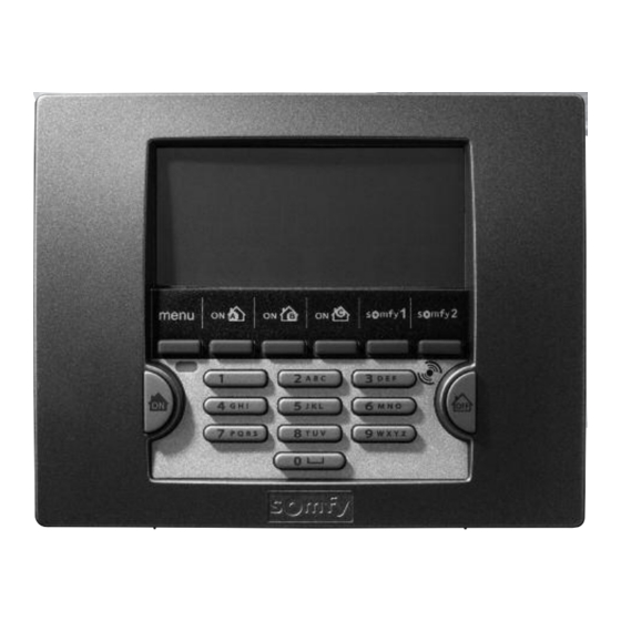
Page 28: Making The System Settings
2 lines of 20 characters Delete an entry Back to previous menu Confirm an entry Somfy 2 automatic Enter or exit menus device control Somfy 1 automatic Part arm the alarm device control Black programming keys... - Page 29 Making the system settings Menu sequence, basic functions It is essential to store: - the codes, - the phone numbers, printed on a grey background below - the PIN, - the date and time. page 1 Language English Installer code User code 1 User code 2 2 Codes...
- Page 30 Making the system settings 1. Language for keypad display and voice synthesis French is already selected. L a ng u ag e 2. Customisation of codes on keypad All the codes to be stored must be between 0001 and 9998. You should enter these immediately 2 C od e s 2 OK on the memo sheet in the operating manual.
- Page 31 Making the system settings 3. Phone 3 OK 3 P ho n e To store: 31 Alarm sending - either 4 telephone numbers for sending synthesised voice alarm messages by fixed telephone line (PSTN), – or 4 SMS numbers for sending alarm SMSs by GSM, –...
- Page 32 Making the system settings To store 4 SMS numbers for sending alarm SMSs by the fixed telephone line (PSTN) or GSM, to 312 SMS sending neighbours’, family members’ or friends’ mobile or fixed telephones (for fixed telephones, the alarm SMS will be voice synthesised by the operator): 3121 SMS number 1 Empty The new phone number is stored...
- Page 33 Making the system settings Used to check the status of the fixed telephone line and perform sending tests before the system 33 PSTN settings is armed for the first time. Used to check whether or not the PSTN module is connected: 330 PSTN module status Present Missing...
- Page 34 Making the system settings Used to identify the name of the strongest GSM network at the installation, find out the status of 34 GSM settings the GSM line, make SIM card settings and send a test alarm SMS to the 1 number.
- Page 35 Making the system settings 4. Storing the date and time This menu makes it possible to timestamp alarm messages. 4 OK 4 D at e a nd t i m e If the installation includes an IP module and your central unit/phone dialer is connected to a broadband router/modem, the central unit/phone dialer will automatically manage the summer/winter clock change.
- Page 36 Shutter prog. 7611 Light prog. Programming of 7612 automatic devices Gate prog. 7613 Garage door prog. 7614 Somfy 1 key Somfy 2 key Shutters on intrusion 7641 Control of automatic devices Shutters down Shutters on arming 7642 Shutters on smoke 7651...
- Page 37 Making the system settings 7. Settings for advanced functions 7 S et t i ng s 7 OK Used to set the entry delay for the intrusion detectors in zone A with delayed triggering, with a 71Entry delay value of 1 to 60 seconds before triggering of the alarm: The new delay period is stored Interval: (45 seconds by default)
- Page 38 Making the system settings To set the sound level of all the sirens in the installation: 736Siren level Level 1, 2 or 3 1 OK Low level 2 OK Medium level (default) 3 OK High level To cause a message to be entered in the event log on the LCD keypad if jamming is detected: 74Intf detect.
- Page 39 LCD keypad to these automatic devices; - to create roller shutter up/down scenarios or light on/off scenarios. First of all, read the instructions for the Somfy motor/receiver that you want to trigger (see section “Storing remote controls“).
- Page 40 You can use this menu to cause the roller shutters to come up: 765Shutters up - either when smoke is detected by the Somfy smoke detector (ref. 2400443), to enable easy evacuation, - or when the alarm is disarmed when you return home...
- Page 41 Making the system settings You can use this menu to programme the automatic arming of the system and simulate presence in the 77Time prog. dwelling (lighting or roller shutters). To programme one or two automatic armings (for example: at 8:50 in the morning, 771Arming when everyone has left the house, or at 23:00 in the evening when everyone is in bed).
- Page 42 Making the system settings To simulate a presence by programming the switching on and off of a light. 772Light Time light is switched on, time slot 1: 7721Light ON 1 07:30 Light on time stored 06:45 Time light is switched off, time slot 1: 7722Light OFF 1 07:30 Light on time...
- Page 43 Making the system settings PRESENCE SIMULATION USING ROLLER SHUTTERS: to simulate a presence by programming 773Roller shutters the opening and closing of roller shutters. Time at which the roller shutters come up: 7731Shutters up 18:30 Up time stored 08:30 Time at which the roller shutters come down: 7732Shutters down 18:30 Down time stored...
- Page 44 Making the system settings This menu is used to read the IP address of the central unit/phone dialer and the IP address of the 78IP settings broadband router/modem. IP address of the central unit/phone dialer (record on the memo sheet in the 780Phone dialer IP address operating manual).
-
Page 45: Recording A Customised Alarm Message Announcement
Recording a customised alarm message announcement This message can only be recorded if your central unit/phone dialer is equipped with a PSTN module. The customised alarm message is used to introduce the alarm message sent by voice synthesis. It can only be recorded remotely as follows: Connect to the phone dialer from another telephone line or mobile telephone Press OFF + enter user code 1 on the LCD keypad (or OFF on the remote control). -
Page 46: Testing The Installation
Testing the installation Testing the detectors With the alarm disarmed, For a 2-minute period, the indicator on press the detector the detector lights up on each detection Door opening/closing …BEEP! …BEEP! Movement in front of the detector For the outdoor movement detector, refer to the corresponding instructions. Testing the sirens and the phone dialer Arm the alarm The sirens are activated for... -
Page 47: Remote Settings Via Telephone
Remote settings via telephone Making settings remotely via telephone is particularly recommended if settings are changed later after initial installation. The “ Remote settings via telephone “ function is only guaranteed for France Telecom lines. It is only possible if your customer agrees. The customer must have entered OFF + user code 1 on his/her LCD keypad before you enter your installer code remotely. -
Page 48: Summary Of System Operation
Summary of system operation... - Page 49 Summary of system operation...
-
Page 50: Replacing The Batteries
How do you know if a device’s batteries are discharged? icon on the LCD keypad flashes. BEEP! BEEP! BEEP! BEEP! The following message is displayed: A rapid series of BEEPs! is heard when the alarm is armed. BATTERY / LINK Identifying the affected device If the indicator does not light up, the batteries need To identify the device, go to menu... -
Page 51: Resetting The System
If a remote control or badge is lost or stolen Erase the corresponding device in menu “ 5Device list “, see page 34. If the installer code is lost Deactivate the installation’s tamper switch (to avoid triggering the alarm). Press OFF until the ...BEEP! on the central unit/phone indicator goes out. -
Page 52: Troubleshooting
Troubleshooting You can find the solutions to the most frequent problems on our web site www.somfy.xx, section FAQ (Frequently Asked Questions)..on a siren Problem Solutions Have you installed batteries in the siren? Are the batteries in good condition and positioned correctly? - Page 53 Troubleshooting ... on an opening detector Problem Solutions Have you installed the battery in the detector? Is it stored? No beep when the detector button Is the battery in good condition and positioned correctly ( on top)? is pressed The detector cannot be stored in the Have you installed the battery in the correct position in the detector? central unit/phone dialer when the Have you switched the central unit/phone dialer to storage mode?
-
Page 54: Table Of Specifications
Table of specifications Operating Tamper Device Action temperature switch Triggers a low level alarm for 10 seconds (95 dB) followed by 110 seconds Opening Indoor siren Indoor + 5 to + 40 °C at full power (112 dB) or triggering of the alarm for 2 minutes at low level Removal 95 dB depending on the settings. -
Page 55: Index
Table of specifications Operating Tamper Device Operation Action temperature switch Can only be used on an analogue line with DTMF code-compatible dialling for the PSTN module. Remote settings in voice mode via DTMF codes (requires a France Telecom line). Making local settings using the LCD keypad or by computer, depending on version. - Page 56 MOTORISED ROLLER MOTORISED BLINDS MOTORISED SHUTTERS GARAGE DOORS MOTORISED GATES LIGHTING WIRELESS RADIO ALARM SYSTEM Customer service for professionals: For all additional information: www somfy xx...
Need help?
Do you have a question about the Protexial and is the answer not in the manual?
Questions and answers