Advertisement
Quick Links
S
UPERMICR
R
C7X99-OCE / C7X99-OCE-F
Q
r
g
r
. 1.0
uICk
eferenCe
uIde
ev
C
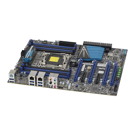
Motherboard Layout and Features
S8
JBR1
1-2:NORMAL
2-3:BIOS RECOVERY
JPAC1
JIPMB1
JSTBY1
JPAC1
LEDM1
1-2 ENABLE
2-3 DISABLE
JBR1
SW_BIOSRC
S4
S10
S7
S6
S5
S9
BT1
IPMI CODE
MAC CODE
C7X99-OCE-F
2
REV:1.00
BAR CODE
DESIGNED IN USA
LE2
C
S11
19
CHASSIS INTRUSION
JL1
JBT1
LED4
JSD1
SP1
FAN3
s-SATA0
I-SATA4
I-SATA2
I-SATA0
s-SATA2
JUSB30_I2
MH10
s-SATA3
s-SATA1
I-SATA5
I-SATA3
I-SATA1
Note for VGA Cards: For a single VGA card, install the VGA card into the SLOT6 (x16) slot. For CrossFireX™ mode (two VGA
cards linked), install one card each into SLOT6 (x16) and SLOT4 (x16) slots.
Note for Intel CPUs: PCIe Slot#1 (x4) and Slot#4 (x16) are disabled when an Intel Core i7-5820K is installed. This is due to
the CPU having a limitation of 28 PCIe lanes, compared to 40 with other CPU models.
CPU Installation
Heatsink Installation
Align Socket Keys
Note: Graphics shown in this quick reference guide are for illustration only. Your components may or may not look exactly the same as drawings shown in this guide.
C
I
ontaCt
nformatIon
• www.supermicro.com (Email: support@supermicro.com)
• Manuals: http://www.supermicro.com/support/manuals
• Drivers & Utilities: ftp://ftp.supermicro.com
• Safety: http://www.supermicro.com/about/policies/safety_information.cfm
I/O BACK PANEL
AUDIO_FP
VGA
LAN2
LAN1
C7X99-OCE-F
USB 14/15(3.0)
USB 12/13(3.0)
USB 10/11(3.0)
Only
HD AUDIO
MH9
JPUSB1
USB14/15 WAKE UP
JPL1
FAN5
JPUSB1
1-2 ENABLE
2-3 DISABLE
JPL2
FAN4
1-2 ENABLE
2-3 DISABLE
DIMMA1
DIMMA2
DIMMB1
DIMMB2
CPU
Intel Core i7
LGA 2011-3
JPW2
MH11
DIMMD2
DIMMD1
DIMMC2
DIMMC1
:SATA DOM POWER
4
1
JPW1
JPI2C1
:PWR I2C
= mounting hole
Front Panel Control (JF1)
Screw #4
20
19
Ground
NMI
Screw #2
X
X
Power LED
Vcc
HDD LED
Vcc
NIC1 LED
Vcc
Screw #3
Vcc
NIC2 LED
OH/Fan Fail LED
Vcc
Power Fail LED
Vcc
#3~4
Reset Button
Ground
Power Button
Ground
#1~2
2
1
P
C
aCkage
ontents
(Applies to individual-pack only)
• One (1) Supermicro Motherboard
• Six (6) SATA Cables (single packed/boxed only)
• Two (2) SATA Cables (bulk packed only)
Jumpers, Connectors and LED Indicators
Jumpers
Jumper
Description
JBT1*
Clear CMOS (on board)
(See Chpt. 2)
JI
C1/JI
C2
SMB to PCI Slots
Off (Disabled)
2
2
JPAC1
Audio Enable
Pins 1-2 (Enabled)
JPL1/JPL2
LAN1/LAN2 Enable
Pins 1-2 (Enabled)
JPME2
Intel Recovery Mode
Pins 1-2 (Normal)
JWD1
Watch Dog Enable
Pins 2-3 (NMI)
JBR1
Restores the BIOS firmware from a USB
Pins 1-2 (Normal), set switch to pins 2-3
memory device (SUPER.ROM)
to recover BIOS
JPUSB1
USB Wake Up Enable (USB14/15)
Pins 1-2 (Enabled)
JPB1
BMC Enable/Disable (
Pins 1-2 (Enabled)
C7X99-OCE-F only)
JPG1
Onboard VGA Enable (
Pins 1-2 (Enabled)
C7X99-OCE-F only)
Connectors and Switches
Connector
Description
I/O Back Panel
See Back Panel I/O Connectors, below right
Audio FP
Front Panel Audio Header
BT1
Onboard Battery
Fan 1,2,3,4,5
System/CPU Fan Headers (Fan1: CPU Fan)
JD1
Speaker/buzzer (Pins 1~4: External Speaker, Pins 3~4: Buzzer)
JF1
Front Panel Control Header
JL1
Chassis Intrusion Header
JPW1
24-pin ATX Main Power Connector (Required)
JPW2
+12V 4-pin CPU power Connector (Required)
JSD1
SATA DOM (Disk On Module) Power Connector
JSTBY1
Standby Power Header
SP1
Internal Speaker/Buzzer
I-SATA0~5
(Intel X99) SATA 3.0 Ports 0~5 (6Gb/sec), Supports RAID 0, 1 ,5 & 10
s-SATA0~3
(Intel X99) SATA 3.0 Ports 0~3 (6Gb/sec), no RAID functions
USB 16/17
Front Panel Accessible USB 3.0 Headers 16/17
OC FRONT PANEL
Header for the Over-Clocking Control Panel
S4
Power Button
S11
BIOS Restore
S5, S6, S7
Over-Clocking Buttons OC1(15%), OC2(20-25%), OC3 (User-Defined in BIOS)
S9
Home Button, Default setting (non-OC)
S10
Memory Overclocking Button
S8
Clear CMOS Button (on board)
JPI2C1
Power Supply SMBbus I2C Header.
JTPM1
Trusted Platform Module Header
COM1
Serial Port Header for COM1
JIPMB1
System Management Bus header (for IPMI only)
LED Indicators
LED
Description
Color/State
Status
LEDM1
BMC Heartbeat*
Green: Blinking
BMC Normal
LE2
Power LED
Geen: Steady
System On/Running
LED4
Status Display
Digital Readout
Download the status codes below**
(C7X99-OCE only)
*
For the C7X99-OCE-F, reboot time may be longer after clearing CMOS. This is due to the additional IPMI functions.
**
Download the AMI status codes at
http://www.ami.com/support/doc/ami_aptio_4.x_status_codes_pub.pdf
Note: Refer to Chapter 2 of the User Manual for detailed information on jumpers, connectors, and LED indicators.
• One (1) I/O Shield
• One (1) Quick Reference Guide
• One (1) Driver CD (C7X99-OCE single packed/boxed only)
Memory Support
The C7X99-OCE(-F) supports up to 64GB of Unbuffered (UDIMM) DDR4 non-
Default
ECC 2133~3000(OC) MHz in 8 memory slots. Populating these DIMM modules
with a pair of memory modules of the same type and same size will result in
interleaved memory, which will improve memory performance.
Note: For memory optimization, use only DIMM modules that have been validated by Supermicro.
For the latest memory updates, please refer to our website at http://www.supermicro.com/
products/motherboard.
DIMM Memory Installation
DIMMA1 (Blue Slot)
DIMMA2
DIMMB1 (Blue Slot)
DIMMB2
DIMMD2
DIMMD1 (Blue Slot)
DIMMC2
DIMMC1 (Blue Slot)
Memory Population Guidelines
When installing memory modules, the DIMM slots should be populated in the follow-
ing order: DIMMA1, DIMMB1, DIMMC1, DIMMD1 then DIMMA2, DIMMB2, DIMMC2,
DIMMD2.
•
Always use DDR4 DIMM modules of the same size, type and speed.
Recommended Population (Balanced)
DIMMA1
DIMMB1
DIMMC1
DIMMD1
DIMMA2
4GB
4GB
4GB
4GB
4GB
4GB
4GB
4GB
4GB
4GB
4GB
4GB
4GB
4GB
4GB
4GB
Note: Up to 64GB of memory are supported. See chapter 2 of the User Manual for
complete memory population information.
Back Panel I/O Connectors
A. PS/2 Keyboard/Mouse Port
B. USB 3.0 Port 14
C. USB 3.0 Port 15
D. VGA Port*
E. Gb LAN Port 1 (shared IPMI*)
F. USB 3.0 Port 10
G. USB 3.0 Port 11
*
C7X99-OCE-F only
*
A
C7X99-OCE-F only
D
B
C
Note: Refer to Chapter 2 of the User Manual for detailed information on memory support and CPU/
motherboard installation instructions.
I/O Back Panel
CPU
DIMMB2
DIMMC2
DIMMD2
Total System
Memory
8GB
16GB
4GB
24GB
4GB
4GB
4GB
32GB
H. Gb LAN Port 2
L. Center/LFE Out
I. USB 3.0 Port 12
M. Surround Out
J. USB 3.0 Port 13
N. S/PDIF Out
K. Clear CMOS
O. Line In
P. Line Out
Q. Mic In
L
O
E
H
HD Audio
K
M
P
I
F
Q
N
G
J
Advertisement


Need help?
Do you have a question about the C7X99-OCE and is the answer not in the manual?
Questions and answers