Sign In
Upload
Manuals
Brands
Supermicro Manuals
Motherboard
C7Z170-OCE
Supermicro C7Z170-OCE Manuals
Manuals and User Guides for Supermicro C7Z170-OCE. We have
3
Supermicro C7Z170-OCE manuals available for free PDF download: User Manual, Quick Reference Manual
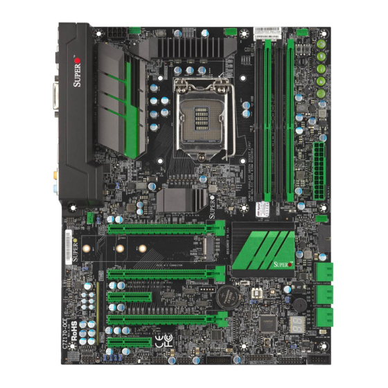
Supermicro C7Z170-OCE User Manual (153 pages)
Brand:
Supermicro
| Category:
Motherboard
| Size: 15 MB
Table of Contents
Conventions Used in the Manual
4
Battery Handling
5
Standardized Warning Statements
5
Product Disposal
6
Contacting Supermicro
8
Table of Contents
10
Chapter 1 Introduction
15
Overview
15
Chipset Overview
15
Motherboard Features
16
Special Features
18
PC Health Monitoring
18
Fan Status Monitor with Firmware Control
18
Environmental Temperature Control
18
System Resource Alert
19
ACPI Features
19
Power Supply
20
Super I/O
20
Chapter 2 Installation
27
Installation Components and Tools Needed
27
Static-Sensitive Devices
28
Precautions
28
Unpacking
28
Processor and Heatsink Installation
29
Installing the LGA1151 Processor
29
Installing an Active CPU Heatsink with Fan
32
Removing the Heatsink
34
Installing DDR4 Memory
35
DIMM Installation
35
Removing Memory Modules
35
Memory Support
36
Memory Population Guidelines
37
Motherboard Installation
38
Tools Needed
38
Location of Mounting Holes
38
Installing the Motherboard
39
Connectors/Io Ports
40
Back I/O Panel
40
Universal Serial Bus (USB)
41
Ethernet Port
42
Back Panel High Definition Audio (HD Audio)
42
S/PDIF Port
43
VESA® Displayport
43
HDMI Port
43
DVI-D Port
43
Front Control Panel
44
Jf1 Header Pins
44
Front Control Panel Pin Definitions
45
Power LED
45
Hdd Led
45
Nic1/Nic2 (Lan)
45
Overheat (Oh)/Fan Fail
45
Reset Button
46
Power Button
46
Connecting Cables
47
ATX Main PWR & CPU PWR Connectors (JPW1 & JPW2)
47
Fan Headers
48
Chassis Intrusion
48
Internal Buzzer
49
Speaker
49
Onboard Power LED
50
Serial Port
50
DOM PWR Connector
51
Spdif out
51
Standby Power Header
52
Connector
52
Front Panel Audio Header
53
TPM Header
54
Jumper Settings
55
Explanation of Jumpers
55
LAN Enable/Disable
55
Clear CMOS & JBT1
56
PCI Slot SMB Enable
56
Audio Enable
57
BIOS Recovery Switch
57
Manufacturing Mode
58
Watch Dog
58
Power Button (POWER BUTTON)
59
BIOS Restore (BIOS RESTORE)
59
Onboard Indicators
60
LAN Leds
60
Onboard Power LED
60
Status Display
61
Led
61
SATA Connections
62
SATA Connections (I-SATA0~I-SATA5)
62
Chapter 3 Troubleshooting
63
Troubleshooting Procedures
63
Before Power on
63
Memory Errors
64
Technical Support Procedures
65
Frequently Asked Questions
66
Battery Removal and Installation
67
Proper Battery Disposal
67
Battery Installation
68
Returning Motherboard for Service
68
Chapter 4 BIOS
69
Introduction
69
How to Change the Configuration Data
70
How to Start the Setup Utility
70
System Information
71
Cpu
72
CPU Configuration
73
Hardware Prefetcher
74
Debug Interface
76
Power and Performance
77
CPU - Power Management Control
77
View/Configure Turbo Options
78
CPU VR Settings
79
Acoustic Noise Settings
80
Core/Ia VR Settings
81
GT-Sliced VR Settings
83
C3 Latency Control (MSR 0X60A)
86
C6/C7 Short Latency Control (MSR 0X60B)
86
C6/C7 Long Latency Control (MSR 0X60C)
86
Custom P-State Table
87
CPU Lock Configuration
87
GT-Power Management
88
CPU Overclocking
89
Acoustic Noise Settings
95
Core/Ia VR Settings
96
Memory
99
Memory Overclocking
100
3Rd Timing
103
Advanced
107
Boot Feature
107
Serial Port Console Redirection
110
System Agent (SA) Configuration
114
Graphics Configuration
115
Primary Display
115
Internal Graphics
116
Graphics Overclocking
117
GT-Sliced VR Settings
118
SATA and RST Configuration
124
PCH FW Configuration
125
USB Configuration
126
Pcie/Pci/Pnp Configuration
127
Network Stack
128
Security
129
Administrator Password
129
Secure Boot
130
Key Management
131
Authorized Signatures
132
Thermal
134
System Temperature
134
Save & Exit
136
Boot Mode Select
136
FIXED BOOT ORDER Priorities
136
Legacy Boot Option #1~#8
136
NETWORK Drive BBS Priorities
136
Boot Option #1
136
Boot Override
136
IBA CL Slot 00FE V0110
137
Launch EFI Shell from Filesystem Device
137
BIOS Update
138
Start Update
138
Appendix A BIOS Error Beep Codes
141
BIOS Error Beep Codes
141
Appendix B Software Installation Instructions
143
Installing Drivers
143
Configuring Superdoctor ® V
144
Appendix C UEFI BIOS Recovery Instructions
147
An Overview to the UEFI BIOS
147
How to Recover the UEFI BIOS Image (-The Main BIOS Block
147
To Recover the Main BIOS Block Using a USB-Attached Device
148
Appendix D Dual Boot Block
151
Introduction
151
BIOS Boot Block
151
BIOS Boot Block Corruption Occurrence
151
D-2 Steps to Reboot the System by Switch JBR1
152
Advertisement
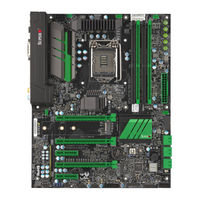
Supermicro C7Z170-OCE User Manual (133 pages)
Brand:
Supermicro
| Category:
Motherboard
| Size: 11 MB
Table of Contents
Manual Organization
3
Checklist
4
Conventions Used in the Manual
4
Standardized Warning Statements
5
Battery Handling
5
Product Disposal
6
Contacting Supermicro
8
Where to Find more Information
9
Table of Contents
10
Chapter 1 Introduction
15
Overview
15
About this Motherboard
15
Chipset Overview
15
Intel Z170 Express Chipset Features
15
Motherboard Features
16
Special Features
18
Recovery from AC Power Loss
18
PC Health Monitoring
18
Fan Status Monitor with Firmware Control
18
Environmental Temperature Control
18
System Resource Alert
19
ACPI Features
19
Slow Blinking LED for Suspend-State Indicator
19
Power Supply
20
Super I/O
20
Chapter 2 Installation
27
Installation Components and Tools Needed
27
Static-Sensitive Devices
28
Precautions
28
Unpacking
28
Processor and Heatsink Installation
29
Installing the LGA1151 Processor
29
Installing an Active CPU Heatsink with Fan
32
Removing the Heatsink
34
Installing DDR4 Memory
35
DIMM Installation
35
Removing Memory Modules
35
Memory Support
36
Memory Population Guidelines
37
Motherboard Installation
38
Tools Needed
38
Location of Mounting Holes
38
Installing the Motherboard
39
Connectors/Io Ports
40
Back I/O Panel
40
Universal Serial Bus (USB)
41
Ethernet Port
42
Back Panel High Definition Audio (HD Audio)
42
S/PDIF Port
43
VESA® Displayport
43
HDMI Port
43
DVI-D Port
43
Front Control Panel
44
Jf1 Header Pins
44
Front Control Panel Pin Definitions
45
Power LED
45
Hdd Led
45
Nic1/Nic2 (Lan)
45
Overheat (Oh)/Fan Fail
45
Reset Button
46
Power Button
46
Connecting Cables
47
ATX Main PWR & CPU PWR Connectors (JPW1 & JPW2)
47
Fan Headers
48
Chassis Intrusion
48
Internal Buzzer
49
Speaker
49
Onboard Power LED
50
Serial Port
50
DOM PWR Connector
51
Spdif out
51
Standby Power Header
52
Connector
52
Front Panel Audio Header
53
OC Front Panel
53
TPM Header
54
Jumper Settings
55
Explanation of Jumpers
55
LAN Enable/Disable
55
Clear CMOS & JBT1
56
PCI Slot SMB Enable
56
Audio Enable
57
BIOS Recovery Switch
57
Manufacturing Mode
58
Watch Dog
58
Power Button (POWER BUTTON)
59
BIOS Restore (BIOS RESTORE)
59
Onboard Indicators
60
LAN Leds
60
Onboard Power LED
60
Status Display
61
Led
61
SATA Connections
62
SATA Connections (I-SATA0~I-SATA5)
62
The OC Front Control Panel (Optional)
63
Overclocking Buttons (OC1, OC2, OC3)
63
Clear CMOS and Reset
63
Boot BIOS Switch
63
BIOS Recovery
63
Front USB Port
63
Installing the OC Front Control Panel
64
Chapter 3 Troubleshooting
65
Troubleshooting Procedures
65
Before Power on
65
No Power
65
No Video
66
Memory Errors
66
When the System Is Losing the Setup Configuration
66
Technical Support Procedures
67
Frequently Asked Questions
68
Battery Removal and Installation
69
Battery Removal
69
Proper Battery Disposal
69
Returning Motherboard for Service
70
Battery Installation
70
Chapter 4 BIOS
71
Introduction
71
How to Change the Configuration Data
72
How to Start the Setup Utility
72
Saving and Loading
73
System Information
76
Processor/Cpu
79
Overclocking Lock
81
Hardware Prefetcher
81
Power Management
83
Extra Performance
85
Memory
86
Memory Information
86
Booting
88
Boot Device Settings
88
Boot Configuration
89
Input/Output
91
Option Rom Execution
95
Network Stack
96
Super Io Configuration
99
Serial Port 1 Configuration
99
Hardware Monitor
100
Management
103
Console Redirection
104
Chipset
110
System Agent
110
Primary Display
111
Internal Graphics
112
Security
113
Administrator Password
114
Key Management
115
Authorized Signatures
117
Recovery
119
Appendix A BIOS Error Beep Codes
121
Appendix B Software Installation Instructions
123
Installing Drivers
123
Configuring Superdoctor ® III
124
Appendix C UEFI BIOS Recovery Instructions
127
An Overview to the UEFI BIOS
127
How to Recover the UEFI BIOS Image (-The Main BIOS Block
127
To Recover the Main BIOS Block Using a USB-Attached Device
128
Appendix D Dual Boot Block
131
Introduction
131
BIOS Boot Block
131
BIOS Boot Block Corruption Occurrence
131
D-2 Steps to Reboot the System by Switch JBR1
132
Supermicro C7Z170-OCE Quick Reference Manual (1 page)
Motherboard Layout and Features
Brand:
Supermicro
| Category:
Motherboard
| Size: 1 MB
Advertisement
Advertisement
Related Products
Supermicro C7Z170-SQ
Supermicro C7Z170-M
Supermicro Supero C7Z97-MF
Supermicro Supero C7Z97-M
Supermicro C7Z87
Supermicro C7Z270-CG-L
Supermicro C7Z270-PG
Supermicro C7Z270-CG
Supermicro C7Z87-OCE
Supermicro C7Z270-CG-M
Supermicro Categories
Server
Motherboard
Computer Hardware
Chassis
Switch
More Supermicro Manuals
Login
Sign In
OR
Sign in with Facebook
Sign in with Google
Upload manual
Upload from disk
Upload from URL