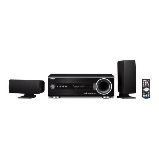
Yamaha YHT-S300 Service Manual

Yamaha YHT-S300 Service Manual

Subwoofer integrated receiver sr-300, speakers ns-br300/ns-p705/ns-b380
Hide thumbs Also See for YHT-S300:

Advertisement

HOME THEATER PACKAGE
SUBWOOFER INTEGRATED RECEIVER
SPEAKERS
The YHT-S300 consists of the SR-300 and NS-B380.
The YHT-S350 consists of the SR-300 and NS-P705.
The YHT-S400 consists of the SR-300 and NS-BR300.
The YHT-S1400 consists of the SR-300, BD-S1065 and NS-B380.
This service manual is for the SR-300/NS-BR300/NS-P705/NS-B380.
For service manual of the BD-S1065, please refer to the following publication number:
This manual has been provided for the use of authorized YAMAHA Retailers and their service personnel.
It has been assumed that basic service procedures inherent to the industry, and more specifi cally YAMAHA Products, are already known
and understood by the users, and have therefore not been restated.
WARNING:
IMPORTANT:
The data provided is believed to be accurate and applicable to the unit(s) indicated on the cover. The research, engineering, and service
departments of YAMAHA are continually striving to improve YAMAHA products. Modifications are, therefore, inevitable and
specifi cations are subject to change without notice or obligation to retrofi t. Should any discrepancy appear to exist, please contact the
distributor's Service Division.
WARNING:
IMPORTANT:
■ CONTENTS
TO SERVICE PERSONNEL ............................................2
FRONT PANELS .........................................................4-5
REAR PANELS ...........................................................6-8
REMOTE CONTROL PANELS .......................................9
SPECIFICATIONS / 参考仕様 ................................. 10-13
INTERNAL VIEW .......................................................... 14
サービス時の注意事項 ................................................ 14
UPDATING FIRMWARE /
ファームウェアのアップデート ............................20-26
1 0 1 1 6 1
YHT-S300/YHT-S350/YHT-S400/YHT-S1400
NS-BR300/NS-P705/NS-B380
BD-S1900/BD-S1065: 1011 5 1
IMPORTANT NOTICE
Failure to follow appropriate service and safety procedures when servicing this product may result in personal injury,
destruction of expensive components, and failure of the product to perform as specifi ed. For these reasons, we advise
all YAMAHA product owners that any service required should be performed by an authorized YAMAHA Retailer or
the appointed service representative.
The presentation or sale of this manual to any individual or fi rm does not constitute authorization, certifi cation or
recognition of any applicable technical capabilities, or establish a principle-agent relationship of any form.
Static discharges can destroy expensive components. Discharge any static electricity your body may have
accumulated by grounding yourself to the ground buss in the unit (heavy gauge black wires connect to this buss).
Turn the unit OFF during disassembly and part replacement. Recheck all work before you apply power to the unit.
DISPLAY DATA .............................................................52
IC DATA ...................................................................53-65
PIN CONNECTION DIAGRAMS .............................66-67
BLOCK DIAGRAM ..................................................68-69
PRINTED CIRCUIT BOARDS .................................70-78
SCHEMATIC DIAGRAMS .......................................79-85
REPLACEMENT PARTS LIST .............................. 87-100
REMOTE CONTROL ........................................... 101-102
Copyright © 2009
This manual is copyrighted by YAMAHA and may not be copied or
redistributed either in print or electronically without permission.
SR-300
SERVICE MANUAL
ダイアグ(自己診断機能) .....................................31-51
All rights reserved.
P.O.Box 1, Hamamatsu, Japan
'09.11

Advertisement

Table of Contents
loading

Summary of Contents for Yamaha YHT-S300

  • Page 1: Table Of Contents

    This manual has been provided for the use of authorized YAMAHA Retailers and their service personnel. It has been assumed that basic service procedures inherent to the industry, and more specifi cally YAMAHA Products, are already known and understood by the users, and have therefore not been restated.
  • Page 2: To Service Personnel

    SR-300/NS-BR300/NS-P705/NS-B380 ■ TO SERVICE PERSONNEL AC LEAKAGE WALL EQUIPMENT TESTER OR 1. Critical Components Information OUTLET UNDER TEST EQUIVALENT Components having special characteristics are marked must be replaced with parts having specifications equal to those originally installed. 2. Leakage Current Measurement (For 120V Models Only) When service has been completed, it is imperative to verify INSULATING that all exposed conductive surfaces are properly insulated...
  • Page 3: System Composition / システム構成

    SR-300/NS-BR300/NS-P705/NS-B380 ■ SYSTEM COMPOSITION / システム構成 The YHT-S300 consists of the SR-300 and NS-B380. The YHT-S350 consists of the SR-300 and NS-P705. The YHT-S400 consists of the SR-300 and NS-BR300. The YHT-S1400 consists of the SR-300, BD-S1065 and NS-B380. This service manual is for the SR-300/NS-BR300/NS-P705/NS-B380.
  • Page 4: Front Panels

    SR-300/NS-BR300/NS-P705/NS-B380 ■ FRONT PANELS SR-300 U, C, T, A, G, F, L models J model NS-BR300 U, C, T, A, G, F, L, J models...
  • Page 5 SR-300/NS-BR300/NS-P705/NS-B380 NS-P705 J model Left Right NS-B380 G, F, L models...
  • Page 6: Rear Panels

    SR-300/NS-BR300/NS-P705/NS-B380 ■ REAR PANELS SR-300 U, C models T, A, G, F, L models T model G, F models L model A model...
  • Page 7 SR-300/NS-BR300/NS-P705/NS-B380 J model NS-BR300 U, C, T, A, G, F, L, J models...
  • Page 8 SR-300/NS-BR300/NS-P705/NS-B380 NS-P705 J model Left Right NS-B380 G, F, L models...
  • Page 9: Remote Control Panels

    SR-300/NS-BR300/NS-P705/NS-B380 ■ REMOTE CONTROL PANELS FSR30 FSR31 (U, C, T, A, G, F, L models) (J model)
  • Page 10: Specifications / 参考仕様

    SR-300/NS-BR300/NS-P705/NS-B380 ■ SPECIFICATIONS / 参考仕様 ■ Audio Section / オーディオ部 ■ General / 総合 Minimum RMS Output Power / 定格出力 (1 % THD) Power Supply / 電源電圧 FRONT L/R (1 kHz, 6 ohms) U, C models ............AC 120 V, 60 Hz ...................45 W + 45 W T, A, G, F, L models ........
  • Page 11 Type ......2-way acoustic suspension speaker system Non-magnetic shielding type Driver Bluetooth is a registered trademark of Bluetooth SIG and is used by Yamaha Woofer ..........6.5 cm (2-1/2") cone type x 2 in accordance with a license agreement. Bluetooth は、Bluetooth SIG の登録商標でありヤマハはライセンスに基づ...
  • Page 12 SR-300/NS-BR300/NS-P705/NS-B380 • DIMENSIONS / 寸法図 SR-300 NS-P705 Top view Top view Rear view Side view 5 (1/4") 8 (3/8") 32 (1-1/4") (1/8") (3-3/4") (3-3/4") Stand (3-7/8") (3-1/8") (3-7/8") NS-B380 Side view Rear view 10 (3/8") Ø 3.5 mm (1/8"), Hole depth: 13 mm (1/2") 5 (1/4") 15 (5/8") Front view...
  • Page 13 SR-300/NS-BR300/NS-P705/NS-B380 • SET MENU TABLE MENU PARAMETER VALUE [INITIAL VALUE] Adjusting the volume balance during playback 1: SW LEVEL 2: CENTER LEVEL 3: SUR. LEVEL –6 to +6, [0] Adjusting high/low frequency sound (tone control) 4: TONE BASS 5: TONE TREBLE Adjusting the audio delay 6: AUDIO DELAY [AUTO] / 0 to 240 ms (step 10 ms)
  • Page 14: Internal View

    SR-300/NS-BR300/NS-P705/NS-B380 ■ INTERNAL VIEW Rear view POWER (1) P.C.B. FM TUNER INPUT P.C.B. HDMI P.C.B. MAIN P.C.B. POWER (3) P.C.B. WOOFER SW POWER (2) P.C.B. Top view Front view ■ SERVICE PRECAUTIONS / サービス時の注意事項 Precaution for handling measuring instrument 計測器取り扱い上の注意 As the speaker output of SR-300 is B.T.L.
  • Page 15: Disassembly Procedures / 分解手順

    SR-300/NS-BR300/NS-P705/NS-B380 ■ DISASSEMBLY PROCEDURES / 分解手順 Disconnect the power cable from the AC outlet. AC 電源コンセントから、電源コードを抜いてください。 ● Required tools ● 必要なツール Used when removing the front panel unit. フロントパネルユニットを取り外す時に使用します。 • Flatblade screwdriver ・ マイナスドライバー • Metalblade or the like (with wider blade end) ・...
  • Page 16 SR-300/NS-BR300/NS-P705/NS-B380 3. Removal of Shield Frame (Upper/Lower) 3. シールドフレーム(上と下)の外し方 a. Remove CB303 and CB701. (Fig. 2) a. CB303、CB701 を外します。 (Fig. 2) b. Remove 17 screws ( ⑤ ). (Fig. 2) b. ⑤ のネジ 17 本を外します。 (Fig. 2) c. Remove the shield frame (upper/lower). (Fig. 2) c.
  • Page 17 SR-300/NS-BR300/NS-P705/NS-B380 5. Removal of INPUT P.C.B. and FM tuner 5. INPUT、FM チューナーの外し方 a. Remove the pad S and pad LL. (Fig. 3) a. パッド S、パッド LL を取り外します。 (Fig. 3) The pad S/pad LL cannot be reused. ※ パッド S、パッド LL は再利用できません。取り外 When removed, be sure to replace it with new one.
  • Page 18 SR-300/NS-BR300/NS-P705/NS-B380 8. Removal of Front Panel Unit 8. フロントパネルユニットの外し方 The front panel unit is fixed to the cabinet ass’y ※ フロントパネルユニットはダボでキャビネット with dowels. As a flatblade screwdriver is used for ASSY に固定されています。取り外しの際、キャビ removal, use special care not to cause damage to ネット...
  • Page 19 SR-300/NS-BR300/NS-P705/NS-B380 When checking the P.C.B.s: P.C.B. をチェックする場合には: • Spread the rubber sheet and the cloth. Then place ・ ゴムシートと布を敷き、その上にアンプユニットを the amp unit on the cloth and check it. (Fig. 5) 置いてチェックします。 (Fig. 5) • When connecting the flexible flat cable, be careful ・...
  • Page 20: ファームウェアのアップデート

    SR-300/NS-BR300/NS-P705/NS-B380 ■ UPDATING FIRMWARE / ファームウェアのアップデート When the following parts are replaced, the firmware must 下記の部品を交換した場合、ファームウェアを最新バー be updated to the latest version. ジョンにアップデートする必要があります。 Updating method Updating method Writing system Replaced parts using the firmware CD using the PC (RS232C) model name and destination 交換部品...
  • Page 21 SR-300/NS-BR300/NS-P705/NS-B380 ● Connection ● 接続 1. Connect this unit and DVD/CD player as shown 1. 本機と DVD/CD プレーヤーを下記のように接続し below. (Fig. 1) ます。 (Fig. 1) This unit / 本機 DVD/CD player / DVD/CDプレーヤー Optical cable 光ファイバーケーブル Fig. 1 ● Operation Procedures ●...
  • Page 22 SR-300/NS-BR300/NS-P705/NS-B380 6. Press the “PLAY” key of the DVD/CD player. 6. DVD/CD プレーヤーの PLAY キーを押します。 Then writing of the firmware is started. (Fig. 3) ファームウェアの書き込みが開始されます。 (Fig. 3) 7. When writing of the firmware is completed, “Up- 7. フ ァ ー ム ウ ェ ア の 書 き 込 み 完 了 後、 Update date Success”, “Please...”...
  • Page 23 SR-300/NS-BR300/NS-P705/NS-B380 Updating method using PC (RS232C) PC(RS232C)を使用したアップデート方法 ● Required tools ● 必要なツール • Firmware downloader program ..FlashSta.exe ・ プログラム書き込み用プログラム ..FlashSta.exe • Firmware ........yas72_xxx.mot ・ ファームウェア ..........yas72_xxx.mot yas72_xxx.id yas72_xxx.id • RS232C cross cable “D-sub 9 pin female” ・ RS232C クロスケーブル D-sub 9pin メス (Specifications) (仕様)...
  • Page 24 SR-300/NS-BR300/NS-P705/NS-B380 ● Operation procedure ● 操作方法 1. Connect the power cable of this unit to the AC 1. 本機の電源コードを AC コンセントに接続します。 outlet. 本機の電源が入り、マイコンが書き込みモードに The power to this unit is turned on and the なります。 microprocessor is in the writing mode. 2.
  • Page 25 SR-300/NS-BR300/NS-P705/NS-B380 5. Click [Setting], and set the baud rate. (Fig. 4) 5. [Setting]をクリックし、通信速度の設定を行い ます。 (Fig. 4) Reduce the baud rate if a transmission error ※ 送信エラーが多発する場合は、通信速度を下 occurs frequently. げてください。 115200 Fig. 4 6. Click [E.P.R.], then the “Erase” screen appears. 6.
  • Page 26 SR-300/NS-BR300/NS-P705/NS-B380 8. When writing of the firmware is completed, the 8. ファームウェアの書き込みが完了すると、以下の screen appears as shown below. (Fig. 6) 画面が表示されます。 (Fig. 6) Click [OK]. (Fig. 6) [OK]をクリックします。 (Fig. 6) 9. Click [Exit] to end FlashSta.exe. (Fig. 6) 9. [Exit]をクリックして FlashSta.exe を終了します。 (Fig.
  • Page 27: Writing System Model Name And Destination / システムモデル名と仕向け先の書き込み

    指定のダウンロード先から、書き込むテキスト specified source to the PC. ファイルを PC にダウンロードしてください。 xxxxy.txt System model name / システムモデル名 Destination / 仕向け先 300: YHT-S300 u, t, a, g, f, l, j 350: YHT-S350 400: YHT-S400 1400: YHT-S1400 • RS232C cross cable “D-sub 9 pin female”...
  • Page 28 SR-300/NS-BR300/NS-P705/NS-B380 ● Operation procedure ● 操作方法 1. Connect the power cable of this unit to the AC 1. 本機の電源コードを AC コンセントに接続します。 outlet. 本機がスタンバイモードになります。 This unit is in standby mode. 2. RS232C 変 換 ア ダ プ タ ー の リ セ ッ ト ス イ ッ チ 2.
  • Page 29 SR-300/NS-BR300/NS-P705/NS-B380 4. Input “sr300”, and click [OK]. sr300 を入力し、 [OK]をクリックします。 The “Connect To” screen appears. (Fig. 3) 接続の設定 が表示されます。 (Fig. 3) 5. Select “Connect using”. (Fig. 3) 接続方法 を選択します。 (Fig. 3) Select the port of RS-232C, and click [OK]. RS-232C ポートを選択し、 [ OK] をクリックします。 The “Port Settings”...
  • Page 30 (Fig. 5) ます。 (Fig. 5) Destination / 仕向け先 u, t, a, g, f, l, j System model name / システムモデル名 3: YHT-S300 5: YHT-S350 4: YHT-S400 1: YHT-S1400 Fig. 5 9. Click [File] → [Exit] to end HyperTerminal.
  • Page 31: Self-Diagnostic Function / ダイアグ(自己診断機能

    SR-300/NS-BR300/NS-P705/NS-B380 ■ SELF-DIAGNOSTIC FUNCTION / ダイアグ(自己診断機能) There are 23 main menu items, each of which has sub- メ イ ン メ ニ ュ ー は 23 個 あ り、 そ の そ れ ぞ れ に サ ブ メ menu items. ニューがあります。...
  • Page 32 SR-300/NS-BR300/NS-P705/NS-B380 Main menu Sub-menu 12 PROTECTION HISTORY 1 HISTORY 1 2 HISTORY 2 3 HISTORY 3 4 HISTORY 4 5 HISTORY RESET 13 DOCK CHECK 1 DOCK CHECK 14 SUBWOOFER CROSS OVER 1 CROSS OVER 150Hz (40–200 Hz) 15 FACTORY PRESET 1 INHIBIT 2 RESERVED 16 SWEEP TEST...
  • Page 33 SR-300/NS-BR300/NS-P705/NS-B380 ● Starting Self-Diagnostic Function ● ダイアグの起動 With this unit in the stand-by mode, press the keys on the スタンバイモードで、リモコンキーを下記の順に押しま remote control in the order as shown below. す。 The self-diagnostic function mode is activated. ダイアグが起動します。 Keys on the remote control / リモコンキー Display / ディスプレイ表示...
  • Page 34 SR-300/NS-BR300/NS-P705/NS-B380 ● Starting Self-diagnostic function in ● プロテクション解除モードでの起動 the protection cancel mode If the protection function works and causes hindrance to プロテクションが動作することにより、故障箇所の診断 trouble shoot, cancel the protection function as described に支障をきたすような場合は、次の方法によりプロテク below, and it will be possible to enter the self-diagnostic ションを解除した状態でダイアグモードに入ることがで...
  • Page 35 SR-300/NS-BR300/NS-P705/NS-B380 ● Canceling Self-diagnostic function ● ダイアグの解除 Before canceling self-diagnostic function, execute ダイアグを解除する前に、メインメニュー No. 15 の setting for FACTORY PRESET of main menu No. 15 FACTORY PRESET(メモリーの初期化禁止/またはメ (Memory initialization inhibited or Memory initialized). モリーの初期化)の設定をします。 In order to keep the user memory preserved, ※...
  • Page 36 SR-300/NS-BR300/NS-P705/NS-B380 ● History of protection function ● プロテクションの履歴 When the protection function has worked, its history is プロテクションが働いた場合、履歴をバックアップして stored in memory with a backup. Even if no abnormality 記憶しています。修理のときに異常が認められなくても、 is noted while servicing the unit, an abnormality which バックアップが残っていれば、お客様のところで起きた has occurred previously can be defined as long as the 異常を区別できます。...
  • Page 37 SR-300/NS-BR300/NS-P705/NS-B380 ● Functions in Self-Diagnostic Function ● ダイアグ中の機能 mode In addition to the self-diagnostic function menu items, ダイアグメニューの他に、以下の機能が動作します。 functions listed below are available. ・ 電源オン/オフ • Power on/off ・ インプットの切り替え • INPUT select ・ マスターボリューム • Master volume 注意: CAUTION: 下記のメニューを選択すると出力レベルが自動的に...
  • Page 38 SR-300/NS-BR300/NS-P705/NS-B380 ● Details of Self-Diagnostic Function menu ● ダイアグメニュー詳細 1. DSP THROUGH 1. DSP THROUGH This menu is used to select the volume level. ボリュームレベルを選択します。 The signal is output in digital full bit without including ヘッドマージンを含まず、デジタルフルビットで出 the head margin. 力されます。 Select the input source using the input key.
  • Page 39 SR-300/NS-BR300/NS-P705/NS-B380 2. FL DISPLAY CHECK 2. FL DISPLAY CHECK This menu is used to check the FL display section/ FL 表示部とインジケーターの動作を確認します。 indicators for displaying/indicating. サブメニュー操作により、表示状態が以下のように Using the sub-menu, the display condition changes 変わります。 as shown below. 2-1. ALL SEGMENTS ON / 全セグメン ト点灯 STATUS indicator: On (Green) STATUS インジケーター:点灯...
  • Page 40 SR-300/NS-BR300/NS-P705/NS-B380 3. TEST TONE 3. TEST TONE When this menu is selected, the volume level ※ このメニューを選択すると、出力レベルが自動的 raises to 30 (-19.0) automatically. に 30(-19.0)に上がります。 The built-in noise generator of DSP outputs the test DSP 内蔵のノイズ発生回路によって、サブメニュー noise through the channels specified by using the で指定したチャンネルへテストノイズが出力されま...
  • Page 41 SR-300/NS-BR300/NS-P705/NS-B380 5. SPEAKER SELECT 5. SPEAKER SELECT Not applied to this model. このモデルには適応されません。 S P S M A L L S P L A R G E 6. AD DATA CHECK 6. AD DATA CHECK This menu is used to display the A/D conversion 本機パネルキー、プロテクションなどを検出してい...
  • Page 42 SR-300/NS-BR300/NS-P705/NS-B380 6-3. 7i / 5i 6-3. 7i / 5i Power supply voltage +7i (for DOCK) 7i: 電源電圧 +7i(DOCK 用) Normal value: 60 to 220 正常値:60 ∼ 220 (Reference voltage: 3.3 V = 255) (基準電圧:3.3 V = 255) Power supply voltage +5i (for DOCK) 5i:...
  • Page 43 SR-300/NS-BR300/NS-P705/NS-B380 6-6. 12 / 26 6-6. 12 / 26 Power supply voltage +12D (for digital 12: 電源電圧 +12D(デジタル回路用) circuit) 正常値:97 ∼ 156 Normal value: 97 to 156 (基準電圧:3.3 V = 255) (Reference voltage: 3.3 V = 255) 26: 電源電圧 +26D(デジタルアンプ用) Power supply voltage +26D (for digital 正常値:45 ∼...
  • Page 44 SR-300/NS-BR300/NS-P705/NS-B380 DEVICE CHECK 7. DEVICE CHECK This menu is used to check the communication and 各デバイス間のとバスラインの接続のチェックしま bus line connection between devices. す。 Checking is executed automatically and when an 自動で順次チェックを行い、エラー時には下記のエ error is found, it is indicated by each corresponding ラーメッセージを表示します。 error message as shown below.
  • Page 45 ※ 図中の数値は参考例です。 reference. 9-1. MICROPROCESSOR VERSION / DESTINATION / SYSTEM MODEL 9 - 1 B 1 0 2 Y F 4 0 System model / システムモデル名 YHT-S300 YHT-S350 YHT-S400 140: YHT-S1400 Destination / 仕向け先 U, T, A, G, F, L, J is displayed.
  • Page 46 SR-300/NS-BR300/NS-P705/NS-B380 12. PROTECTION HISTORY 12. PROTECTION HISTORY This menu is used to display the history of protection プロテクション履歴が表示されます。 function. Example 12-1 History 1 / 履歴 1 1 2 - 1 I 0 0 1 H Example 12-2 History 2 / 履歴 2 1 2 - 2 N o P R T Example 12-3 History 3 / 履歴...
  • Page 47 SR-300/NS-BR300/NS-P705/NS-B380 13. DOCK 13. DOCK This menu is used to check the DOCK connector iPod 本体無しで、DOCK コネクターの検査を行うメ without the iPod itself. ニューです。 With the power to this unit turned off, short between 本機の電源を切った状態で、DOCK コネクターの 14 pins No. 14 (TX) and No. 18 (RX), between pins No. ピン(TX)と...
  • Page 48 SR-300/NS-BR300/NS-P705/NS-B380 14. SUBWOOFER CROSS OVER 14. SUBWOOFER CROSS OVER This menu is used to set the crossover frequency of サブウーファーと L/R/ センターチャンネルのクロス SUB-WOOFER and L/R/Center channels. オーバー周波数を設定します。 This setting is retained until the initializing is この設定状態は、初期化が行われるまで保持されま performed. す。 Select the main menu using “ ( )” (up) and “ ( )” リモコンの...
  • Page 49 SR-300/NS-BR300/NS-P705/NS-B380 16. SWEEP TEST 16. SWEEP TEST When this menu is selected, the volume level ※ こ の メ ニ ュ ー を 選 択 す る と、 出 力 レ ベ ル が 60 raises to 60 (-4.0). (-4.0)に上がります。 Input the sweep signal (20 Hz to 2 kHz, 450 mVrms, アナログ入力端子へスイープ信号(20 Hz ∼...
  • Page 50 SR-300/NS-BR300/NS-P705/NS-B380 20. POWER OFF FACTOR HISTORY 20. POWER OFF FACTOR HISTORY This menu is used to display the history of power off 電源オフ要因履歴が表示されます。 factor. Example 20-1 History 1 / 履歴 1 2 0 - 1 N O O F F Example 20-2 History 2 / 履歴...
  • Page 51 SR-300/NS-BR300/NS-P705/NS-B380 21. CEC UPDATE 21. CEC UPDATE Not applied to this model. このモデルには適応されません。 C E C U P D A T E 22. VIDEO DEBUG 22. VIDEO DEBUG Not applied to this model. このモデルには適応されません。 2 2 - 1 V i d b g O F F 2 2 - 1 V i d b g O N 23.
  • Page 52: Display Data

    SR-300/NS-BR300/NS-P705/NS-B380 ■ DISPLAY DATA ● V851 : HNA-17SM07T (POWER P.C.B.) ● PIN CONNECTION Pin No. 65-57 Connection Pin No. Connection Pin No. Connection Note: 1) F1, F2 ..Filament pin 2) 1G – 17G ..Grid pin 3) P1 – P35 ..Anode pin 4) NP ..
  • Page 53: Ic Data

    SR-300/NS-BR300/NS-P705/NS-B380 ■ IC DATA IC309: D70YE101BRFP266 (MAIN P.C.B.) Decoder/Post processor * No replacement part available. / サービス部品供給なし SPI0_SIMO EM_CKE SPI0_SOMI/I2C0_SDA EM_CLK AXR0[0] EM_WE_DQM[1] AXR0[1] EM_D[8] AXR0[2] AXR0[3] EM_D[9] EM_D[10] AXR0[4] AXR0[5]/SPI1_SCS EM_D[11] AXR0[6]/SPI1_ENA AXR0[7]/SPI1_CLK EM_D[12] EM_D[13] EM_D[14] AXR0[8]/AXR1[5]/SPI1_SOMI EM_D[15] AXR0[9]/AXR1[4]/SPI1_SIMO EM_D[0] AXR0[10]/AXR1[3] EM_D[1]...
  • Page 54 SR-300/NS-BR300/NS-P705/NS-B380 Function Name TYPE PULL GPIO Detail of Function (P.C.B.) AHCLKX0/AHCLKX2 – McASP0 and McASP2 transmit master clock AMUTE0 – McASP0 mute output AMUTE1 – McASP1 mute output AHCLKX1 – McASP1 transmit master clock ACLKX1 – McASP1 transmit bit clock CVDD ACLKR1 –...
  • Page 55 SR-300/NS-BR300/NS-P705/NS-B380 Function Name TYPE PULL GPIO Detail of Function (P.C.B.) EM_D[10] – EMIF data bus [lower 16-Bits] EM_D[9] – EMIF data bus [lower 16-Bits] CVDD EM_D[8] – EMIF data bus [lower 16-bits] EM_WE_DQM[1] – Write enable or byte enable for EM_D [15:8] DVDD EM_CLK –...
  • Page 56 SR-300/NS-BR300/NS-P705/NS-B380 Function Name TYPE PULL GPIO Detail of Function (P.C.B.) 123 CVDD 124 VSS 125 DVDD McASP0 serial data 8 or McASP1 serial data 5 or SPI1 data pin slave 126 /SPI1_SOMI – out master in McASP0 serial data 9 or McASP1 serial data 4 or SPI1 data pin slave in 127 /SPI1_SIMO –...
  • Page 57 SR-300/NS-BR300/NS-P705/NS-B380 IC851: M66003-0131FP (POWER P.C.B.) FL display driver Display code CGROM SEG00 (35-bit x 166) (8-bit x 60) Segment SEG25 Code output write SEG26 circuit CGROM SEG34 dot data Serial data (35-bit x 16) write receive Code/ circuit SDATA command SEG35 control circuit...
  • Page 58 SR-300/NS-BR300/NS-P705/NS-B380 Pin No. Port Name Function Name Detail of Function Vcc1 Positive power supply for internal logic. SEG34 SEG33 SEG32 SEG31 SEG30 Segment output Connect to segment (anode) pins of VFD. SEG29 SEG28 SEG27 SEG26 Vcc2 Positive power supply for DIG and SEG outputs. SEG25 SEG24 SEG23...
  • Page 59 SR-300/NS-BR300/NS-P705/NS-B380 IC316: M3087BFKBGP (MAIN P.C.B.) Microprocessor Port P0 Port P1 Port P2 Port P3 Port P4 Port P5 Port P6 < > < > Peripheral Functions Clock Generation Circuit A/D Converter: 1 circuit Timer (16-bit) Standard: 10 inputs COUT Timer A: 5-channel Maximum: 34 inputs On-chip Oscillator Timer B: 6-channel...
  • Page 60 SR-300/NS-BR300/NS-P705/NS-B380 Function Name Port Name Detail of Function (P.C.B.) TXD4 P96/ANEX1/ TXDi Asynchronous data output for iPod TXD4/SDA4/ SRXD4 Unconnected P95/ANEX0/CLK4 Unconnected P94/DA1/TB4in/ CTS4/RTS4/SS4 TB3in Detection of iPod loaded in dock P93/DA0/TB3in/ iPDET Low when iPod is loaded in dock CTS3/RTS3/SS3 P92/TB2in/TXD3/ SDA3/...
  • Page 61 SR-300/NS-BR300/NS-P705/NS-B380 Function Name Port Name Detail of Function (P.C.B.) INT0 CEC_INT HDMI CEC microprocessor interrupt signal P82/INT0 P81/TA4in/U/ INPC15/OUTC15/ DSP_N_SPIRDY DSP SPIRDY signal CTS5/RTS5/ RTP23 RXD5 P80/TA4out/U/ DSP_DIR_MISO Synchronous data input for DSP/DIR ISRXD0/RXD5 CLK5 P77/TA3in/ INPC14/OUTC14/ DSP_DIR_SCK Synchronous clock output for DSP/DIR ISCLK0/CLK5/ RTP22 TXD5...
  • Page 62 SR-300/NS-BR300/NS-P705/NS-B380 Function Name Port Name Detail of Function (P.C.B.) SDA0 HDMI_SDA (Open (Open I2C SDA output for HDMI RX/TX CEC microprocessor P63/TXD0/SDA0/ SRXD0/IrDAout Drain) Drain) SCL0 P62/RXD0/SCL0/ HDMI_SCL (Open (Open I2C SCL output for HDMI RX/TX CEC microprocessor Drain) Drain) STXD0/IrDAin /INT_SD_C_ Detection of D-AMP Cch TAS5342 shutdown...
  • Page 63 SR-300/NS-BR300/NS-P705/NS-B380 Function Name Port Name Detail of Function (P.C.B.) Unconnected P43/A19 74 Vcc2 Vcc2 [MCU] Unconnected P42/A18 76 Vss Unconnected P41/A17 Unconnected P40/A16 Unconnected P37/A15(/D15) Unconnected P36/A14(/D14) Unconnected P35/A13(/D13) /MUTE_PWM Mute signal for TAS5086 P34/A12(/D12) /PDN_PWM Power down signal for TAS5086 P33/A11(/D11) /RST_PWM Reset signal for TAS5086...
  • Page 64 SR-300/NS-BR300/NS-P705/NS-B380 Function Name Port Name Detail of Function (P.C.B.) ON/OFF control of switching power supply IC P-CON P20/A0/(/D0)/ H: ON L: OFF AN20 INT5 INT_PDN_DET Interrupt input for detection of power down P17/D15/INT5 INT4 /INT_PSW Interrupt input for detection of power ON/OFF SW P16/D14/INT4 INT3 INT_REM...
  • Page 65 SR-300/NS-BR300/NS-P705/NS-B380 Function Name Port Name Detail of Function (P.C.B.) AN153 KEY1 AD KEY1 input P153/AN153/ CTS5/RTS5 ISRXD0 P152/AN152/ E2R_MISO EEPROM synchronous data input ISRXD0/RXD5 ISCLK0 FLD_E2R_SCK Synchronous clock output for FL DRIVER IC/EEPROM P151/AN151/ ISCLK0/CLK5 130 Vss ISTXD0 FLD_E2R_MOSI Synchronous data output for FL DRIVER IC/EEPROM P150/AN150/ ISTXD0/TXD5 132 Vcc1...
  • Page 66: Pin Connection Diagrams

    SR-300/NS-BR300/NS-P705/NS-B380 ■ PIN CONNECTION DIAGRAMS • ICs FA5511N-D1-TE1 D70YE101BRFP266 KIA78L05F-RTF/P LC72725KM-UY-TLM-E M3087BFKBGP SiI9233ACTU 1: OUTPUT 2: COMMON (CASE) 3: INPUT LC89058WD-E LE25LA322M-TLM-E LMV431AIMF M12L16161A-7TG M66003-0131FP-R TPS54331DR MIP2F40MS MN103SFD7GYAD NJM2750M-TE2 NJM2820F TE1 NJM2904M (TE3) NJM2867F3-05 NJM431U PCM1803DBR PQ012FZ01ZPH PQ033EZ01ZP PQ1CG41H2FZ R1172S121D-E2-F PQ018EZ01ZP TC74VHC541FT 1: REFERENCE...
  • Page 67 SR-300 • Diodes • Transistors 1SS355 D1FK60-5063 D1NL20U-5083 D3S4M-5002P7.5 2SA1037K 2SC1740S 2SC1815 Y 2SC2412K 2SC4081 T106 D1FL20U-5063 D1NS4-5070 Anode Anode Anode Cathode Cathode Cathode D5S9M D5SBA60 5A 600V HZU8.2B1 TRF-E MTZJ27D 2SK3523-01R 3LN01C-TB-E CPH3205 DTC144EKA IMX1 D15XB60-7001 15A HZU10B1 TRF-E 2SK3876-01R Anode Anode...
  • Page 68: Block Diagram

    SR-300 ■ BLOCK DIAGRAMS Audio/Video/Control Supply Section Block Diagram → MAIN SCHEMATIC DIAGRAM HDMI IN SPEAKER OUTPUT HDMI OUT → HDMI 10MHz SCHEMATIC DIAGRAM POWER → SCHEMATIC DIAGRAM FG1,2 → T702 POWER SCHEMATIC DIAGRAM IC706,Q706 ANALOG MICROPROCESSOR IC703,Q704 INPUT IC707 D729 T701 IC712...
  • Page 69 SR-300 Power Supply Section Block Diagram → MAIN SCHEMATIC DIAGRAM IC302 W301 +26D D-Amp Power Stage TAS5342 → POWER (2) POWER (1) IC303 SCHEMATIC DIAGRAM D-Amp → Power Stage SCHEMATIC DIAGRAM TAS5342 T951 V150 IC312 Regulator D-Amp for Filament FL Display Power Stage and VP TAS5342...
  • Page 70: Printed Circuit Boards

    SR-300 ■ PRINTED CIRCUIT BOARDS INPUT P.C.B. (Side A) ANALOG INPUT No replacement part available. サービス部品供給なし DIGITAL IN DOCK PJ601 CB601 POINT A XL601 (Pin 14 of IC603) IC601 IGND FM TUNER IGND IC605 IC604 DET OUT DGND Rch OUT Vdd select DGND Lch OUT...
  • Page 71 SR-300 INPUT P.C.B. (Side B) G, F models • Semiconductor Location Ref no. Location D1603 Q1602...
  • Page 72 SR-300 • Semiconductor Location POINT D 1 / IC316 (+3.3M), 2 / IC316 (/RESET) Ref no. Location Ref no. Location Ref no. Location Ref no. Location Ref no. Location D306 IC303 IC310 IC316 Q307 D307 IC305 IC311 IC317 Q308 MAIN P.C.B. (Side A) SPEAKER unit IC301...
  • Page 73 SR-300 MAIN P.C.B. (Side B) • Semiconductor Location Ref no. Location D321 Q304 Q305 Q310 Q311...
  • Page 74 SR-300 Circuit No. U, C T, A, G, F, L TH701 TH702 POWER (1) P.C.B. (Side A) C770 C775 X : NOT USED S6.3 O : USED/APPLICABLE SGND SGND HDMI (W1) SGND S3.3 S3.3 MAIN (CB308) IC703 S6.3 P-CON /RES PDET S3.3 SGND...
  • Page 75 SR-300 POWER (1) P.C.B. (Side B) • Semiconductor Location Ref no. Location D702 D706 D716 D717 D720 D721 D724 D727 D731 D733 D737 IC701 IC708 IC701 IC710 IC711 Q701 Q704 Q706 Q707 Q708 T, A, G, F, L models T, A, G, F, L models Q953...
  • Page 76 SR-300 POWER (2) P.C.B. (Side A) + VOLUME - INPUT SW852 SW853 SW854 STATUS indicator CB954 CB953 MAIN (CB309) MAIN (CB307) POWER (3) P.C.B. (Side A) SPEAKRS W931 • Semiconductor Location Ref no. Location MAIN (CB303) D859...
  • Page 77 SR-300 POWER (2) P.C.B. (Side B) POWER (3) P.C.B. (Side B) • Semiconductor Location Ref no. Location D951 D952 D953 D954 D955 IC851 Q855 Q862 Q863 Q864 Q951 Q952...
  • Page 78 SR-300 POINT E XL1 (Pin 5 of IC1) HDMI P.C.B. HDMI P.C.B. (Side A) (Side B) POINT F XL2 (Pin 83 of IC7) No replacement part available. サービス部品供給なし DGND BUSY_FLASH CLK_FLASH RXF_FLASH TXF_FLASH CNVss /RES DGND PRV_5H PRV_HDMI DGND PON_1.8V DGND CEC_N_RST SDA2...
  • Page 79: Schematic Diagrams

    SR-300/NS-BR300/NS-P705/NS-B380 SCHEMATIC DIAGRAMS INPUT CB603 IC603 12.3 To FM TUNER (G, F models) 12.3 12.3 POINT A XL601 (Pin 14 of IC603) Page 83 13.5 13.5 to POWER (1)_CB705 W1601 12.3 IC605 12.3 IC601 LEGULATOR DOCK AUDIO INPUT SELECTOR Page 82 to MAIN_CB310 13.5 No replacement part available.
  • Page 80 SR-300/NS-BR300/NS-P705/NS-B380 MAIN 1/3 IC301: TAS5086DBT PWM processor 12.3 12.3 DVDD DVSS 24.7 DVSS_ESD VR_DIG Power VR_ANA Supply L’ PWM1 VR_OSC 26.6 AVDD 26.6 AVSS_PLL VREG_EN R’ PWM2 Chan. 13.3 SDIN1 Serial SDIN2 Data SDIN3 Interface SDIN4 PWM3 13.3 SDIN4 L’ Channel Down- 26.6...
  • Page 81 SR-300/NS-BR300/NS-P705/NS-B380 MAIN 2/3 To MAIN 3/3 IC318 POINT B XL301 (Pin 29 of IC305) To MAIN 3/3 To MAIN 1/3 CB305 Page 79 to INPUT_CB606 IC307 SDRAM No replacement part available. サービス部品供給なし REGULATOR IC308 IC310 CB306 IC305: LC89058WD-E IC308: PQ033EZ01ZP IC309: D70YE101BRFP266 IC311: M12L16161A-7TG IC318: TC74VHC157FT...
  • Page 82 SR-300/NS-BR300/NS-P705/NS-B380 POINT D 1 / IC316 (+3.3M), 2 / IC316 (/RESET) POINT C XL303 (Pin 20 of IC316) MAIN 3/3 IC316 IC316 (+3.3M) (+3.3M) IC316 IC316 (/RESET) (/RESET) CB309 POWER ON POWER OFF POWER ON 12.3 Page 84 -32.2 to POWER (2)_CB954 : LE25LA322M-TLM-E 32 k-bit serial SPI EEPROM CB308...
  • Page 83 SR-300/NS-BR300/NS-P705/NS-B380 POWER 1/2 AC6.6 CB704 26.6 26.6 26.6 (109.0) Page 80 CB701 to MAIN_W301 AC IN (317.7) 26.4 (468.1) (108.0) 21.6 (317.1) 13.6 (317.1) (1.3) (1.3) CONTROLLER (1.7) 22.6 -0.5 -0.5 IC704 (1.2) IC709 IC712 IC701 (2.6) (4.0) (5.0) (1.2) (15.0) (15.0) (15.1)
  • Page 84 SR-300/NS-BR300/NS-P705/NS-B380 POWER 2/2 IC851: M66003-0131FP-R 18 digit 5 x 7 segment VFD controller/driver Display code CGROM (35-bit x 166) SEG00 (8-bit x 60) Segment SEG25 Code write output SEG26 circuit CGROM Serial dot data SEG34 data write (35-bit x 16) receive Code/ SDAT...
  • Page 85 SR-300/NS-BR300/NS-P705/NS-B380 HDMI POINT E XL1 (Pin 5 of IC1) POINT F XL2 (Pin 83 of IC7) HDMI OUT HDMI IN CEC CONTROLLER REGULATOR HDMI TRANSMITTER HDMI RECEIVER Page 82 to MAIN_CB311 No replacement part available. サービス部品供給なし No replacement part available. サービス部品供給なし...
  • Page 86: Replacement Parts List

    SR-300/NS-BR300/NS-P705/NS-B380 ■ REPLACEMENT PARTS LIST • ELECTRICAL COMPONENT PARTS WARNING ● Components having special characteristics are marked and must be replaced with parts having specifications equal to those originally installed. ● 印のある部分は、安全確保部品を示しています。部品の交換が必要な場合、パーツリストに記載されている部品を使用し てください。 ● 部品価格ランクは、予告なく変更することがあります。 ABBREVIATIONS IN THIS LIST ARE AS FOLLOWS: C.A.EL.CHP : CHIP ALUMI.ELECTROLYTIC CAP L.EMIT...
  • Page 87 SR-300/NS-BR300/NS-P705/NS-B380 P.C.B. INPUT Ref No. Part No. Description Remarks Markets 部 品 名 ランク WS706600 P.C.B. INPUT JUCTAL PCB INPUT WS706700 P.C.B. INPUT PCB INPUT CB602 VB390400 CN.BS.PIN ベースピン CB603 VM859500 CN.BS.PIN FFCコネクター CB604 V2305400 CN.BS.PIN 28P TE コネクタベースポスト CB606 V2304800 CN.BS.PIN コネクタベースポスト C1603 US135100 C.CE.CHP 0.1uF チップセラコン...
  • Page 88 SR-300/NS-BR300/NS-P705/NS-B380 P.C.B. INPUT and P.C.B. MAIN Ref No. Part No. Description Remarks Markets 部 品 名 ランク IC601 YA167A00 IC NJM2750M-TE2 アナログIC IC602 YA712A00 IC TPS54331 DC/DC 電源IC * IC603 X8235A00 IC LC72725KM IC IC604 X7357A00 IC PCM1803DBR IC * IC605 X7444A00 IC KIA78L05F-RTF/P 電源IC...
  • Page 89 SR-300/NS-BR300/NS-P705/NS-B380 P.C.B. MAIN Ref No. Part No. Description Remarks Markets 部 品 名 ランク C393 US061220 C.CE.CHP 22pF 50V B チップセラコン C394 US135100 C.CE.CHP 0.1uF チップセラコン C395 US065100 C.CE.CHP 0.1uF 50V B チップセラコン C396 US135100 C.CE.CHP 0.1uF チップセラコン C397 US145100 C.CE.CHP 0.1uF チップセラコン...
  • Page 90 SR-300/NS-BR300/NS-P705/NS-B380 P.C.B. MAIN Ref No. Part No. Description Remarks Markets 部 品 名 ランク C506 UF148100 C.EL.CHP 100uF チップケミコン C507 US063100 C.CE.CHP 1000pF 50V B チップセラコン C508 US062100 C.CE.CHP 100pF 50V B チップセラコン C509 US063100 C.CE.CHP 1000pF 50V B チップセラコン C510 US062100 C.CE.CHP 100pF 50V B チップセラコン...
  • Page 91 SR-300/NS-BR300/NS-P705/NS-B380 P.C.B. MAIN and P.C.B. POWER Ref No. Part No. Description Remarks Markets 部 品 名 ランク C697 US135100 C.CE.CHP 0.1uF チップセラコン C698 US064100 C.CE.CHP 0.01uF 50V B チップセラコン C699 US135100 C.CE.CHP 0.1uF チップセラコン D306-307 VT332900 DIODE 1SS355 ダイオード D321 VV220700 DIODE.SHOT RB501V-40 ショットキーダイオード...
  • Page 92 SR-300/NS-BR300/NS-P705/NS-B380 P.C.B. POWER Ref No. Part No. Description Remarks Markets 部 品 名 ランク * C720-721 WS765200 C.CE.SAFTY 0.022uF 275V 規格認定コンデンサ C723-724 WH035900 C.CE.SAFTY 1000pF 250V 規格認定コンデンサ C725 US064100 C.CE.CHP 0.01uF 50V B チップセラコン C726 US046100 C.CE.CHP チップセラコン C728 US046100 C.CE.CHP チップセラコン C729 WK583700 C.EL 2200uF...
  • Page 93 SR-300/NS-BR300/NS-P705/NS-B380 P.C.B. POWER Ref No. Part No. Description Remarks Markets 部 品 名 ランク * C952 WS618900 C.EL 100uF ケミコン * C953 WS036400 C.PP 1800pF 100V PPコン * C954 WS618500 C.EL 470uF ケミコン D701 WP006400 DIODE.BRG D15XB60-7001 15A ダイオードブリッジ D701 VN953300 DIODE.BRG D5SBA60 5A 600V UCTAGFL...
  • Page 94 SR-300/NS-BR300/NS-P705/NS-B380 P.C.B. POWER and P.C.B. HDMI Ref No. Part No. Description Remarks Markets 部 品 名 ランク * R726 WH016300 R.MTL.PLAT 0.033Ω 金属板抵抗 * R726 WS278200 R.MTL.PLAT 0.056Ω TAGFL 金属板抵抗 R771-772 VP941400 R.MTL.OXD 3.3KΩ 酸化金属被膜抵抗 R773 VT267900 R.MTL.OXD 1.8KΩ 酸化金属被膜抵抗 * R777 WF548800 R.WW 0.12Ω...
  • Page 95 SR-300/NS-BR300/NS-P705/NS-B380 P.C.B. HDMI Ref No. Part No. Description Remarks Markets 部 品 名 ランク C101 US135100 C.CE.CHP 0.1uF チップセラコン C102 WD758300 C.CE.CHP 10uF チップセラコン C103 US135100 C.CE.CHP 0.1uF チップセラコン C104-106 US063100 C.CE.CHP 1000pF 50V B チップセラコン C107 WD758300 C.CE.CHP 10uF チップセラコン C108 US135100 C.CE.CHP 0.1uF チップセラコン...
  • Page 96 SR-300/NS-BR300/NS-P705/NS-B380 Carbon Resistors Value 1/4W Type Part No. 1/6W Type Part No. Value 1/4W Type Part No. 1/6W Type Part No. 1.0 Ω HJ35 3100 HF85 3100 11 kΩ HF45 7110 HF45 7110 ✻ 1.8 Ω 3180 12 kΩ 7120 7120 HJ35 HJ35...
  • Page 97 SR-300/NS-BR300/NS-P705/NS-B380 1-41 1-40 1-41 1-36 • OVERALL ASS'Y 1-40 1-40 1-46 1-39 1-50 1-34 1-41 1-40 1-36 1-41 1-40 2-20 1-42 1-40 1-42 1-40 2-25 1-20 2-11 2-12 1-43 1-40 1-42 2-20 1-42 2-15 1-40 1-33 1-40 2-13 1-42 2-20 1-41 1-45 1-33...
  • Page 98 SR-300/NS-BR300/NS-P705/NS-B380 Ref No. Part No. Description Remarks Markets 部 品 名 ランク Ref No. Part No. Description Remarks Markets 部 品 名 ランク * 1-1 WS706400 P.C.B. ASS'Y MAIN PCB MAIN 2-25 WG125100 PACKING 4x105x1 パッキン * 1-2 WS706500 P.C.B. ASS'Y HDMI PCB HDMI YC165A00 DRIVER WOOFER 13cm スピーカーユニット...
  • Page 99 SR-300/NS-BR300/NS-P705/NS-B380 • OVERALL ASS'Y NS-BR300/NS-P705/NS-B380 Ref No. Part No. Description Remarks Markets 部 品 名 ランク NS-BR300 * 301 WS689300 BAFFLE ASS'Y バッフルASSY * 301-1 WS338900 PACKING 6x600x1 パッキン * 302 WS689400 CABINET ASS'Y キャビネットASSY * 303 YC164A00 DRIVER FULL-RANGE 10cm 4Ω スピーカーユニット...
  • Page 100: Remote Control

    SR-300/NS-BR300/NS-P705/NS-B380 ■ REMOTE CONTROL SCHEMATIC DIAGRAM In-system programming point IR DIODE M34283G2GP 2 E2 CARR 100 ohms Xout 4.0MHz 1 ohm PANELS FSR30 FSR31 (U, C, T, A, G, F, L models) (J model)
  • Page 101 SR-300/NS-BR300/NS-P705/NS-B380 KEY LAYOUT KEY CODE Key Name Key Code FSR30 FSR31 (U, C, T, A, G, F, L models) (J model) (STANDBY/ON) 78-CC (電源) HDMI1 78-4A HDMI1 HDMI2 78-D0 HDMI2 HDMI3 HDMI3 78-2A 78-4B DOCK ドック 78-BC ANALOG アナログ 78-DE 78-DF MEMORY メモリー...
  • Page 102 SR-300/NS-BR300/NS-P705/NS-B380 MEMO...
  • Page 103 SR-300 NS-BR300/NS-P705/NS-B380...

This manual is also suitable for:

Yht-s400Yht-s350Yht-s1400

Table of Contents