Table of Contents
Advertisement
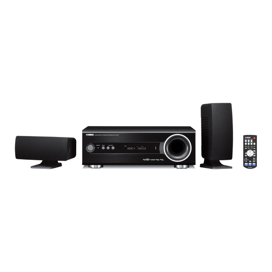
HOME THEATER PACKAGE
SUBWOOFER INTEGRATED RECEIVER
SPEAKERS
The YHT-S300 consists of the SR-300 and NS-B380.
The YHT-S350 consists of the SR-300 and NS-P705.
The YHT-S400 consists of the SR-300 and NS-BR300.
The YHT-S1400 consists of the SR-300, BD-S1065 and NS-B380.
This service manual is for the SR-300/NS-BR300/NS-P705/NS-B380.
For service manual of the BD-S1065, please refer to the following publication number:
This manual has been provided for the use of authorized YAMAHA Retailers and their service personnel.
It has been assumed that basic service procedures inherent to the industry, and more specifi cally YAMAHA Products, are already known
and understood by the users, and have therefore not been restated.
WARNING:
IMPORTANT:
The data provided is believed to be accurate and applicable to the unit(s) indicated on the cover. The research, engineering, and service
departments of YAMAHA are continually striving to improve YAMAHA products. Modifications are, therefore, inevitable and
specifi cations are subject to change without notice or obligation to retrofi t. Should any discrepancy appear to exist, please contact the
distributor's Service Division.
WARNING:
IMPORTANT:
■ CONTENTS
TO SERVICE PERSONNEL ............................................2
SYSTEM COMPOSITION / システム構成 .......................3
FRONT PANELS .........................................................4-5
REAR PANELS ...........................................................6-8
REMOTE CONTROL PANELS .......................................9
SPECIFICATIONS / 参考仕様 ................................. 10-13
INTERNAL VIEW .......................................................... 14
サービス時の注意事項 ................................................ 14
DISASSEMBLY PROCEDURES / 分解手順 ........... 15-19
UPDATING FIRMWARE /
ファームウェアのアップデート ............................20-26
1 0 1 1 6 1
YHT-S300/YHT-S350/YHT-S400/YHT-S1400
NS-BR300/NS-P705/NS-B380
BD-S1900/BD-S1065: 1011 5 1
IMPORTANT NOTICE
Failure to follow appropriate service and safety procedures when servicing this product may result in personal injury,
destruction of expensive components, and failure of the product to perform as specifi ed. For these reasons, we advise
all YAMAHA product owners that any service required should be performed by an authorized YAMAHA Retailer or
the appointed service representative.
The presentation or sale of this manual to any individual or fi rm does not constitute authorization, certifi cation or
recognition of any applicable technical capabilities, or establish a principle-agent relationship of any form.
Static discharges can destroy expensive components. Discharge any static electricity your body may have
accumulated by grounding yourself to the ground buss in the unit (heavy gauge black wires connect to this buss).
Turn the unit OFF during disassembly and part replacement. Recheck all work before you apply power to the unit.
DISPLAY DATA .............................................................52
IC DATA ...................................................................53-65
PIN CONNECTION DIAGRAMS .............................66-67
BLOCK DIAGRAM ..................................................68-69
PRINTED CIRCUIT BOARDS .................................70-78
SCHEMATIC DIAGRAMS .......................................79-85
REPLACEMENT PARTS LIST .............................. 87-100
REMOTE CONTROL ........................................... 101-102
Copyright © 2009
This manual is copyrighted by YAMAHA and may not be copied or
redistributed either in print or electronically without permission.
SR-300
SERVICE MANUAL
システムモデル名と仕向け先の書き込み ..............27-30
ダイアグ(自己診断機能) .....................................31-51
All rights reserved.
P.O.Box 1, Hamamatsu, Japan
'09.11
Advertisement
Table of Contents

Related Manuals for Yamaha YHT-S350


Summarization of Contents
To Service Personnel
Critical Components Information
Information on replacing critical components with identical specifications.
Leakage Current Measurement
Verify insulation of conductive surfaces from supply circuits post-service.
Specifications
Audio Section
Specifications for the audio performance of the unit.
FM Section
Specifications related to the FM tuner functionality.
Speaker Section
Specifications for the speaker system components.
General
General specifications including power, dimensions, and weight.
NS-BR300
Specifications for the NS-BR300 speaker system.
Service Precautions
Precaution for Handling Measuring Instrument
Important precautions when using measuring instruments for service.
Disassembly Procedures
1. Removal of Driver
Step-by-step instructions for removing the speaker driver unit.
2. Removal of Amp Unit
Step-by-step instructions for removing the amplifier unit.
Updating Firmware
Confirmation of Firmware Version and Checksum
How to check firmware version and checksum before/after updates.
Initializing the Back-up IC
Steps to initialize the backup IC after firmware updates.
Required Tools
List of necessary tools and items for firmware updating.
Updating Method Using PC (RS232C)
Required Tools
List of required tools for PC-based firmware updates.
Preparation and Precautions
Preparations and precautions for PC-based firmware updates.
Connection
How to connect the PC and unit for firmware updates.
Writing System Model Name and Destination
Required Tools
Tools needed to write system model name and destination.
Connection
How to connect for writing system model name and destination.
Details of Self-Diagnostic Function Menu
1. DSP THROUGH
Selects the volume level for signal output during diagnostics.
6. AD DATA CHECK
6-3. 7i / 5i
Checks power supply voltage +7i and +5i for DOCK.
6-4. A12 / 1P2
Checks power supply voltage +12A and +1.2D.
6-5. H5 / H18
Checks power supply voltage +5H and +3.3H.
9. MICROPROCESSOR INFORMATION
9-2. CHECKSUM
Displays the checksum value of the microprocessor.
9-3. DSP (TI) VERSION
Displays the firmware version of the DSP.
9-4. CEC VERSION
Displays the firmware version of the CEC.
Display Data
PIN CONNECTION
Pin connection details for ICs.
GRID ASSIGNMENT
Grid assignment for display data.
ANODE CONNECTION
Anode connection details.
IC Data
IC309: D70YE101BRFP266 (MAIN P.C.B.)
Data for IC309, a decoder/post processor.
Pin Connection Diagrams
ICs
Diagrams showing pin connections for various integrated circuits.
Block Diagrams
Audio/Video/Control Supply Section Block Diagram
Block diagram of the audio, video, and control supply sections.
Printed Circuit Boards
INPUT P.C.B. (Side A)
Component layout for the input printed circuit board.
Schematic Diagrams
INPUT
Schematic diagram for the input section.
Remote Control
Schematic Diagram
Schematic diagram for the remote control circuit.
Panels
Visual representation of the remote control panels.
Need help?
Do you have a question about the YHT-S350 and is the answer not in the manual?
Questions and answers