HIKVISION DS-2CE71D0T-PIRL User Manual
Turbo hd d0t pir series turret camera
Hide thumbs
Also See for DS-2CE71D0T-PIRL:
- User manual (13 pages) ,
- User manual (17 pages) ,
- User manual (16 pages)
Table of Contents
Advertisement
Quick Links
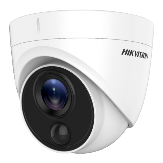
TURBO HD
D0T PIR Series Turret
Camera
User Manual
User Manual
Thank you for purchasing our product. If there are any
questions, or requests, do not hesitate to contact the
dealer.
This manual applies to the models below:
Model
DS-2CE71D0T-PIRL
This manual may contain technical incorrect places or
printing errors, and the content is subject to change
without notice. The updates will be added to the new
version of this manual. We will readily improve or update
the products or procedures described in the manual.
0200001080504
Advertisement
Table of Contents

Related Manuals for HIKVISION DS-2CE71D0T-PIRL


Summary of Contents for HIKVISION DS-2CE71D0T-PIRL
-
Page 1: User Manual
This manual applies to the models below: Model DS-2CE71D0T-PIRL This manual may contain technical incorrect places or printing errors, and the content is subject to change without notice. The updates will be added to the new version of this manual. - Page 2 Regulatory Information FCC Information Please take attention that changes or modification not expressly approved by the party responsible for compliance could void the user’s authority to operate the equipment. FCC compliance: This equipment has been tested and found to comply with the limits for a Class A digital device, pursuant to part 15 of the FCC Rules.
- Page 3 Safety Instruction These instructions are intended to ensure that user can use the product correctly to avoid danger or property loss. The precaution measure is divided into “Warnings” and “Cautions”. Warnings: Serious injury or death may occur if any of the warnings are neglected.
- Page 4 While in delivery, the camera shall be packed in its original packing, or packing of the same texture. Mark Description Table 0-1 Mark Description Mark Description DC Voltage...
-
Page 5: Product Features
1 Introduction 1.1 Product Features The main features are as follows: High performance CMOS sensor IR cut filter with auto switch OSD menu with configurable parameters Auto white balance Internal synchronization SMART IR mode Visible alarm ... -
Page 6: Installation
2 Installation Before you start: Make sure that the device in the package is in good condition and all the assembly parts are included. Make sure that all the related equipment is power-off during the installation. Check the specification of the products for the ... - Page 7 Expansion Bolts Fixing Screws Figure 2-2 Attach the Mounting Base to the Ceiling Note: The supplied screw package contains self-tapping screws, and expansion bolts. For cement wall/ceiling, expansion bolts are required to fix the camera. For wooden wall/ceiling, self- tapping screws are required.
- Page 8 Figure 2-5 The Drill Template 3. Disassemble the inclined ceiling mount by the screw driver. 4. Install the turret camera’s mounting base on the inclined ceiling mount’s cover with three PM4 screws. Figure 2-6 Install Turret Camera’s Mounting Base 5. Install the inclined ceiling mount’s body on the ceiling/wall with four PA4 ×...
- Page 9 2. Drill screw holes and the cable hole (optional) in the ceiling/wall according to the holes of the drill template. Figure 2-9 Drill Template of the Junction Box Note: Drill the cable hole, when adopting the ceiling outlet to route the cable. 3.
-
Page 10: Wall Mounting
2.4 Wall Mounting Before you start: You need to purchase a wall mount separately. Steps: 1. Drill four screw holes in the wall according to the holes of the mount. 2. Install the mount to the wall by aligning the four screw holes of the bracket with expansion screws on the wall. -
Page 11: Menu Description
3 Menu Description Purpose: Call the menu by clicking button on the PTZ Control interface, or call the preset No.95. Steps: 1. Connect the camera with the TVI DVR, and the monitor, shown as the figure 3-1. Figure 3-1 Connection 2. -
Page 12: Video Format
VIDEO FORMAT LANGUAGE EXPOSURE MODE EXPOSURE BACK EXIT SAVE & EXIT MODE BACK DAY/NIGHT EXIT SAVE & EXIT IMAGE MODE WHITE BALANCE BRIGHTNESS CONTRAST SHARPNESS VIDEO SETTINGS SATURATION MIRROR MAIN MENU BACK EXIT SAVE & EXIT WHITE LIGHT PIR LEVEL BACK FUNCTIONS EXIT... - Page 13 3.3 EXPOSURE EXPOSURE MODE You can set the EXPOSURE MODE as GLOBAL, BLC, or DWDR. GLOBAL GLOBAL refers to the normal exposure mode which adjusts lighting distribution, variations, and non-standard processing. BLC (Backlight Compensation) BLC (Backlight Compensation) compensates light to the object in the front to make it clear, but this may cause the over-exposure of the background where the light is strong.
-
Page 14: Video Settings
The Smart IR function is used to adjust the light to its most suitable intensity, and prevent the image from over exposure. The SMART IR value can be adjusted from 0 to 3. The greater the value is, the more obvious effects are. ... - Page 15 the image. The greater the value is, the brighter the image is. CONTRAST This feature enhances the difference in color and light between parts of an image. You can set the CONTRAST value from 1 to 9. SHARPNESS Sharpness determines the amount of detail an imaging system can reproduce.
-
Page 16: Factory Default
Select the ALARM MODE as SOLID. In this way, the white light source turns on, when the PIR module received the alarm signal. In the TIME SETTING you can set the time as 5 s, 10 s, 15 s, 30 s, or 60 s, which means that the solid mode stays for the set time when the camera received one alarm signal.
Need help?
Do you have a question about the DS-2CE71D0T-PIRL and is the answer not in the manual?
Questions and answers