Table of Contents
Advertisement
Quick Links
Premier Elite Speech Module
INSTALLATION INSTRUCTIONS
Introduction
The Premier Elite Speech Module provides four recordable 10 second audio messages, each
message is assigned to a Digi Channel, which in turn can be triggered from one of the many output
functions of the control panel. A COM2400 must be installed to enable the Premier Elite Speech
Module, it will not function with a COM300. Only the first four Digi Channels are used by the
Premier Elite Speech Module. The Premier Elite Speech Module is supported by the following
Texecom control panels:
• Premier Elite all models factory built V3 and later, all models fitted with a DTMF decoder.
If the Speech Module is fitted to a V3 panel that does not have the DTMF decoder chip fitted,
it may not be possible to acknowledge the received calls. This will result in repeated calls
until all programmed dial attempts have been used..
Hardware Identification
Premier Elite 24
F9
Premier Elite 48/88/168 & 640
Box
Tamp
Premier Elite 12-W/24-W/48-W
Tamper
Disable
V
100 V
m = 1 Amp
F2
0.75A 0.3A
V
Batt Charge
F5
F6
PCB Layout and Connections
F7
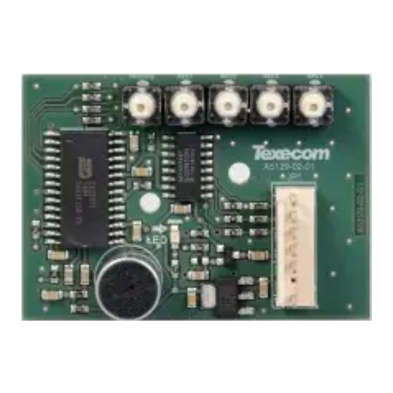
The figure below shows the PCB layout of the Premier Elite Speech Module.
4
1
2
Figure 1. Premier Elite Speech Module PCB Layout
The DTMF chip is located below the Barcode
label and is identified with a green dot.
The DTMF chip is located just below the
digi pins and is identified with a green dot.
F8
BAR CODE
The DTMF chip is located to the left of the
main processor and is identified with a
green dot.
F4
OPTIONS
!
USE WITH
TEXECOM PSU
ONLY
Microphone
Record/Play Indicator
Control panel connector
Record Buttons
3
F9
F3
F5
Tx2 Rx2
Tx1 Rx1
Figure 2. Premier Elite Speech Module Connected to Expansion Port on PCB
Premier Elite Speech Module Installation
To install the Premier Elite Speech Module proceed as follows:
Ensure that all power is removed from the control panel before connecting the Premier Elite
Speech Module.
Plug the Premier Elite Speech Module (see Figure 2) onto the 7 way Expansion Port of the control
panel.
Plug the COM2400 onto the onboard digi pins, and connect to a telephone line. When using an
RJ11 plug, this should be connected before the COM2400 is fitted in place.
Re-apply power to the system and proceed to the next section.
Premier Elite Speech Module Locations
Use the self-adhesive mounting posts to locate the Speech Module as shown.
Premier Elite Small Polymer Housing (e.g. 12-W Live) mount to the rear of the housing
Premier Elite Large Polymer Housing (e.g. 24 & 48-W) mount to the inner wall of the housing
Premier Elite Metal Housing (e.g. 48.88 & 168) mount inside the top of the housing.
F1
Load
Expansion
Defaults
JP7
Advertisement
Table of Contents

Related Manuals for Texecom Premier Elite


Summary of Contents for Texecom Premier Elite
- Page 1 This will result in repeated calls Speech Module. until all programmed dial attempts have been used.. Plug the Premier Elite Speech Module (see Figure 2) onto the 7 way Expansion Port of the control Hardware Identification panel.
- Page 2 Repeat steps 1 to 3 for other messages, if required. Current Consumption (Active): Messages/Channels: Programming the Control Panel The control panel will then need to be programmed correctly in order for the Premier Elite Speech Message Length: 10 Seconds each Module to function as expected:...
Need help?
Do you have a question about the Premier Elite and is the answer not in the manual?
Questions and answers