Table of Contents
Advertisement
Advertisement
Table of Contents

Related Manuals for Eaton 50 VCP-TR16


Summary of Contents for Eaton 50 VCP-TR16
- Page 1 Instructions for the Use, Operation and Maintenance of Types VCP-T and VCP-TR Vacuum Circuit Breakers IB131016EN Effective November 2017 VCP-TR Fixed (up to 25kA) VCP-T Drawout (up to 25kA) VCP-TR Fixed (up to 40kA) VCP-T Drawout (up to 40kA) IB131016EN For more information visit: www.Eaton.com...
- Page 3 RESULT FROM FAILURE TO FOLLOW THE INSTALLATION OR MAINTENANCE PROCEDURES OUTLINED IN THIS MANUAL. PROCEDURES. IF FURTHER INFORMATION IS THESE CIRCUIT BREAKER ELEMENTS ARE SOLD REQUIRED, YOU SHOULD CONTACT EATON PURSUANT TO A NON-STANDARD PURCHASING AGREEMENT WHICH LIMITS THE LIABILITY OF THE MANUFACTURER. Eaton Corporation Moon Township, PA.
-
Page 4: Table Of Contents
Current ......................................45 5-6.1 Plug-in Electrical Accessories..............................46 5-6.2 Internal Electrical Accessories ..............................47 5-6.3 Mechanical Accessories ................................49 SECTION 6: INSPECTION AND MAINTENANCE Introduction ........................................50 Frequency of Inspection and Maintenance ..............................50 For more information visit: www.Eaton.com IB131016EN... - Page 5 Drawout Cassette with Primary Safety Shutters Open Showing Fixed Primary Stabs ................ 28 4-14 Circuit Breaker Shown in Levered Out (DISCONNECT) Position - Correct for Breaker Positioning ........... 28 4-15 Circuit Breaker Shown in Levered In (CONNECT) Position - Incorrect for Breaker Positioning............28 IB131016EN For more information visit: www.Eaton.com...
- Page 6 Undervoltage Release Ratings ................................47 Motor Operator Ratings ................................... 48 Auxiliary Switch Contacts Interrupting Capacities ............................. 48 Inspection and Maintenance Procedures ..............................51 Test Voltage ......................................52 Typical Resistance Measurements ................................55 Troubleshooting Guide ....................................56 For more information visit: www.Eaton.com IB131016EN...
-
Page 7: Section 1: Introduction
PERFORMANCE FOR LONG USEFUL LIFE OF THE CIRCUIT BREAKERS. VCP-T and VCP-TR CIRCUIT BREAKERS ARE PROTECTIVE DEVICES, AS SUCH, THEY ARE MAXIMUM RATED DEVICES. THEREFORE, THEY SHOULD NOT UNDER ANY CIRCUMSTANCES BE APPLIED OUTSIDE THEIR NAMEPLATE RATINGS. IB131016EN For more information visit: www.Eaton.com... -
Page 8: Vcp-T And Vcp-Tr Ratings
Amperes kA Peak Operations kV rms kV rms kV Peak kA rms 10000 50 VCP-T16 4.76 1200 10000 1600 10000 50 VCP-TR16 10000 50 VCP-T20 4.76 1200 10000 1 600 10000 50 VCP-TR20 10000 50 VCP-T25 1200 10000 4.76... - Page 9 Tested for capacitor switching capabilities. “General Purpose” to ANSI C37: Cable charging = 25A. "Definite Purpose" to ANSI C37: Back-to-back equals 250A and 1000A. Ratings of 250 and 1000A cover capacitor bank applications from 75 to 1000A. Inrush current and frequency rating = 18 kApk at 2.4 kHz. IB131016EN For more information visit: www.Eaton.com...
-
Page 10: Types Vcp-T And Vcp-Tr Outlines And Dimensions
Instruction Book Effective: November 2017 Page 4 1-2 Types VCP-T and VCP-TR Outlines and Dimensions (Circuit Breakers and Drawout Cassettes) Figure 1-1 VCP-TR Fixed Breaker Outlines in inches [mm] (except 25kA, 2000/2500A and all 31.5/40kA) For more information visit: www.Eaton.com IB131016EN... - Page 11 Instruction Book Effective: November 2017 Page 5 Figure 1-2 VCP-T Drawout Breaker Outlines in inches [mm] (except 25kA, 2000A and all 31.5/40kA) IB131016EN For more information visit: www.Eaton.com...
- Page 12 Instruction Book Effective: November 2017 Page 6 Figure 1-3 VCP-T Breaker Cassette Outlines in inches [mm] (except 25kA, 2000A and all 31.5/40kA) For more information visit: www.Eaton.com IB131016EN...
- Page 13 Instruction Book Effective: November 2017 Page 7 Figure 1-4 VCP-TR Fixed Breaker Outlines in inches [mm] (Refer to above Applicable Ratings Table) IB131016EN For more information visit: www.Eaton.com...
- Page 14 Instruction Book Effective: November 2017 Page 8 Figure 1-5 VCP-T Drawout Breaker Outlines in inches [mm] (Refer to above Applicable Ratings Table) For more information visit: www.Eaton.com IB131016EN...
- Page 15 Instruction Book Effective: November 2017 Page 9 Figure 1-6 VCP-T Breaker Cassette Outlines in inches [mm] (Refer to above Applicable Ratings Table) IB131016EN For more information visit: www.Eaton.com...
- Page 16 Instruction Book Effective: November 2017 Page 10 REFER TO IL131031EN FOR: VCP-T/T-VAC 31.5kA, 40kA 2000A Cassette Bus Bar Assembly Instructions For more information visit: www.Eaton.com IB131016EN...
-
Page 17: Section 2: Safe Practices
Failure to do so could result in electrical shock supported cart or table. leading to death, severe personal injury and/or property damage. IB131016EN For more information visit: www.Eaton.com... -
Page 18: Section 3: Receiving, Handling And Storage
Record any observed damage for reporting to side and lift up and out on the keyed metal clamps for the transportation carrier and Eaton. All reports should removal (Figure 3-2). The circuit breaker is now ready be as specific as possible and include the order to be removed from its shipping pallet. - Page 19 Instruction Book Effective: November 2017 Page 13 IB131016EN For more information visit: www.Eaton.com...
-
Page 20: Storage
UNDER NO CIRCUMSTANCES SHOULD condensation. Moisture can cause rusting of metal ALTERATIONS BE MADE TO EATON SUPPLIED parts and deterioration of high voltage insulation. A VCP-T OR VCP-TR CIRCUIT BREAKERS UNLESS heat level of approximately 400 watts for each 100... -
Page 21: Typical Breaker And Cassette Weights
(lb) (lb) Breaker Rating Breaker Rating Type (Amps) Type (Amps) Fixed Drawout Cassette Fixed Drawout Cassette 50 VCP-TR16 150 VCP-TR16 1200 1200 50 VCP-T16 1600 150 VCP-T16 1600 50 VCP-TR20 150 VCP-TR20 1200 1200 50 VCP-T20 1600 150 VCP-T20 1600... -
Page 22: Front And Rear Views All Vcp-Tr Fixed (Except 25Ka, 2000/2500A And All 31.5/40Ka)
Front Cover (Figure 3-10 for details) 69C3056G01 3mm Earthed Steel Barrier 69C3104H03 Pole Unit Molding 70D3001G01 Trip Unit Location (Non-Automatic Breaker Shown) Figure 3-5 Front and Rear Views All VCP-TR Fixed (except 25kA, 2000/2500A and all 31.5/40kA) For more information visit: www.Eaton.com IB131016EN... - Page 23 9. Vacuum Interrupter (This is part of the Pole Unit Assembly) 67A3158, 67A3159, or 67A3160 (Depending on the kA and AMP Rating) (Contact your Eaton Sales or Local Eaton Rep. for more information). 10. Primary Disconnect Finger Cluster (1200/1250A Shown) 1200/1250A –...
-
Page 24: Front And Rear Views Drawout Cassette (Except 25Ka, 2000A And All 31.5/40Ka)
4. Rejection Interlock Pins 68B3049G01 5. Interlock Lever (Secondary Contact) - 67A3277H23 6. Earthing Bar - 69C3266H01 Figure 3-7 Front and Rear Views Drawout Cassette (except 25kA, 2000A and all 31.5/40kA, breaker compartment barrier not shown) For more information visit: www.Eaton.com IB131016EN... - Page 25 4. Front Cover (Figure 3-10 for details) 69C3056G01 5. Trip Unit Location (Non-Automatic Breaker Shown) 6. Secondary Disconnect Protective Hood (Umbilical Cord not shown) Harness 69C3261G01 Figure 3-8 Front and Rear Views T-VAC Draw out (25kA, 2000A and all 31.5/40kA) IB131016EN For more information visit: www.Eaton.com...
-
Page 26: Front And Rear Views Drawout Cassette (25Ka, 2000A And All 31.5/40Ka)
Rej. Pin Kit - 68B3049G01 5. Interlock Lever (Secondary Contact) Interlock Lever - 67A3277H23 6. Grounding Bar 7. Position Switches Figure 3-9 Front and Rear Views Drawout Cassette (25kA, 2000A and all 31.5/40kA, breaker compartment barrier not shown) For more information visit: www.Eaton.com IB131016EN... - Page 27 Trip Unit (Optional) - 67A3153XXX / 67A3154XXX Bolt - 70045BB0BG Rating Plug - 5720B93XXX O-Ring - 71070CA009 Trip Unit Test Port 14. Drawout Cradle (Drawout Circuit Breaker Only) - 69C3305G01 (25kA) 69C3305G11 (40kA) Figure 3-10 Typical Front Cover T-VAC IB131016EN For more information visit: www.Eaton.com...
-
Page 28: Section 4: Installation And Wiring
Secondary contacts are dedicated and depends primarily on the circuit breaker rating. Refer to identified. Refer to Figures 5-10 to 5-13 for secondary Figures 1-1 to 1-6 for connection details. For more information visit: www.Eaton.com IB131016EN... -
Page 29: Installing Drawout Circuit Breaker
If they following interlocks to insure safe and proper operation. are not compatible, do not attempt to insert the circuit breaker into the cassette. Contact Eaton for assistance Rejection Interlocks if required. Rejection interlocks are steel pins mounted at the bottom of the drawout circuit breaker and in the base tray (floor) Table 4.1 Cassette Rejection Interlock Pin Locations... -
Page 30: 4-6.2 Circuit Breaker Positioning
HANDLING. REFER TO PARAGRAPH 4-6.4 FOR The metallic primary safety shutters are independently CIRCUIT BREAKER LEVERING DETAILS (FIGURES operated permitting them to be locked in the closed 4-14 AND 4-15). position for safety when the breaker is disconnected or For more information visit: www.Eaton.com IB131016EN... -
Page 31: Position Circuit Breaker With Lifter On Removable Extension Rails
(Figure 4-6). The lifting slings can now be removed from the circuit breaker. IB131016EN For more information visit: www.Eaton.com... -
Page 32: 4-6.3 Drawout Electrical Interfaces
Refer to paragraph 4-6.2 for details on positioning of the circuit breaker for insertion into its Figure 4-9 Shoot Bolt Handle Shown in Position “A” - Shoot cassette. Bolts Retracted Fully Inside Cradle For more information visit: www.Eaton.com IB131016EN... -
Page 33: Secondary Connector Viewed From Rear Of Breaker
Primary connections are made when the spring loaded Interlock Lever finger clusters (disconnects) mounted on the rear of the circuit breaker automatically engage the horizontal stabs rigidly mounted inside the insulating spouts) at the IB131016EN For more information visit: www.Eaton.com... -
Page 34: 4-6.4 Levering Circuit Breaker
HANDLING. REFER TO PARAGRAPH 4-6.2 FOR mechanism is comprised of a drive screw and nut, and is CIRCUIT BREAKER POSITIONING DETAILS AND part of the lower cradle assembly (Figure 4-16). SEE FIGURES 4-14 AND 4-15. For more information visit: www.Eaton.com IB131016EN... -
Page 35: Cradle Mounted Levering Mechanism
(Figure 4-18). The circuit breaker is shown in the CONNECTED position in Figure 4-19. Figure 4-18 Circuit Breaker Connected as Indicated by Fully Connected Position Label Figure 4-16 Cradle Mounted Levering Mechanism IB131016EN For more information visit: www.Eaton.com... -
Page 36: Circuit Breaker Shown In Connect Position With Secondary Connections Made
(Figure 4-16). Once the drive nut is accessible, engage it with the socket and levering crank. Begin levering the For more information visit: www.Eaton.com IB131016EN... -
Page 37: Section 5: Description And Operation
TR circuit breakers are supplied with vertical and fixed type VCP-TR circuit breaker element uses copper horizontal barriers already in place and are required to primary conductors with silver plated joints. be in place before the circuit breaker is put IB131016EN For more information visit: www.Eaton.com... -
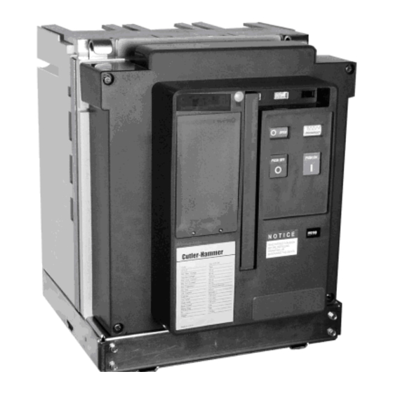
Page 38: Vcp-Tr Fixed Non-Automatic Circuit Breaker (Front Cover Removed)
5. Contact Status (Open-Close) 11. Opening Spring 6. Spring Status (Charged- 12. OFF Key Lock Location Discharged) 13. Motor Cutoff Switch 14. Trip Unit Location Figure 5-2 Typical T-VACR Fixed Non-Automatic Circuit Breaker (Front Cover Removed) For more information visit: www.Eaton.com IB131016EN... -
Page 39: Vcp-T Drawout Circuit Breaker (Front Cover Removed)
19. Levering Drive Nut - Part of 69C3305G11 9. Operations Counter – 592C040H01 20. Push/Pull Handle – Part of 69C3305G11 10. 5A/5B Auxiliary Switch – 698B822H01 Figure 5-3 Typical VCP-T Fixed Drawout Circuit Breaker (Front Cover Removed) IB131016EN For more information visit: www.Eaton.com... -
Page 40: 5-2.1 Contact Erosion Indicator (Up To 25Ka)
A great deal of effort has been spent in the design of all Eaton vacuum circuit breakers, in order to eliminate the need for field adjustments of wipe or stroke. Refer to paragraph 6-7 for details on visually inspecting contact wipe. -
Page 41: Stored Energy Mechanism
An Figure 5-6 Breaker Closing Springs Being Manually electrical operator is used to automatically charge the Charged closing springs. Refer to paragraph 5-3.2 for more details. IB131016EN For more information visit: www.Eaton.com... -
Page 42: 5-3.2 Electrical Operation
(Figure 5- 8). The key interlock can utilize Ronis, Castell or Kirk devices. This mechanical interlock feature prevents the circuit breaker from closing. Figure 5-8 Typical Cover Mounted Key Interlock For more information visit: www.Eaton.com IB131016EN... -
Page 43: Connection Diagrams
- 250 milliseconds 5-4.2 SECONDARY CONNECTIONS Each secondary wiring point is identified and dedicated to a specific function. The wiring points are finger safe Figure 5-14 Secondary Connectors Shown Mounted without Secondary Protective Hood In Place IB131016EN For more information visit: www.Eaton.com... -
Page 44: Vcp-T And Vcp-Tr Non Trip Unit Connection Diagram
Instruction Book Effective: November 2017 Page 38 Figure 5-10 VCP-T and VCP-TR Non Trip Unit Connection Diagram For more information visit: www.Eaton.com IB131016EN... -
Page 45: Vcp-T And Vcp-Tr With 520V Trip Unit Connection Diagram
Instruction Book Effective: November 2017 Page 39 Figure 5-11 VCP-T and VCP-TR with 520V Trip Unit Connection Diagram IB131016EN For more information visit: www.Eaton.com... -
Page 46: Vcp-T And Vcp-Tr With 1150V Trip Unit Connection Diagram
Instruction Book Effective: November 2017 Page 40 Figure 5-12 VCP-T and VCP-TR with 1150V Trip Unit Connection Diagram For more information visit: www.Eaton.com IB131016EN... -
Page 47: 5-12A Vcp-T And Vcp-Tr With 520Mcv Trip Unit Connection Diagram
Instruction Book Effective: November 2017 Page 41 Figure 5-12A VCP-T and VCP-TR with 520MCV Trip Unit Connection Diagram IB131016EN For more information visit: www.Eaton.com... -
Page 48: Vcp-T Drawout Umbilical Cord And Connector Wiring Diagram
Instruction Book Effective: November 2017 Page 42 Figure 5-13 VCP-T Drawout Umbilical Cord and Connector Wiring Diagram For more information visit: www.Eaton.com IB131016EN... -
Page 49: Top View Secondary Connectors
Instruction Book Effective: November 2017 Page 43 Figure 5-15 Top View Secondary Connectors Figure 5-18 AMP Secondary Wiring Removal Tool (AMP#305 183) IB131016EN For more information visit: www.Eaton.com... -
Page 50: Sensors
Table 5.1. The two models (Model 520V and Model 1150V) are not interchangeable in the field. A functional local test can be performed through the trip Contact Eaton for upgrading to Model 520V or Model unit’s test receptacle (Figure 5-19). A small hand held 1150V. -
Page 51: 5-5.2 Rating Plug
Table 5.2 Current Sensors and Matching Rating Plugs Current Rating in Amperes 1000 1200 1250 1600 2000 2500 ---- IB131016EN For more information visit: www.Eaton.com... -
Page 52: 5-6.1 Plug-In Electrical Accessories
70% (Figure 5-24 and Table 5.5). If the release is not energized to 85% of its supply voltage, the circuit breaker cannot be reclosed electrically or manually. The undervoltage release device is always optional. For more information visit: www.Eaton.com IB131016EN... -
Page 53: 5-6.2 Internal Electrical Accessories
240 Vac 204 - 264 84 - 144 400 VA 10VA The trip indicator is available with or without a SPST overcurrent trip switch. This switch only changes state with the trip indicator. IB131016EN For more information visit: www.Eaton.com... -
Page 54: Rugged Motor Operator
Table 5.7 Auxiliary Switch Contacts Interrupting Capacities Control Circuit Voltage Continuous Current (amperes) 120 Vac 240 Vac 24 Vdc 48 Vdc 125 Vdc 250 Vdc Non-inductive Circuit Interrupting Capacity in Amperes Inductive Circuit Interrupting Capacity in Amperes For more information visit: www.Eaton.com IB131016EN... -
Page 55: 5-6.3 Mechanical Accessories
The mechanical interlock holds one or more circuit breakers tripped (prevents closure) Figure 5-28 Door Escutcheon and Gasket Figure 5-27 Pushbutton Cover Mounted IB131016EN For more information visit: www.Eaton.com... -
Page 56: Section 6: Inspection And Maintenance Introduction
Periodic inspections and associated maintenance are essential for the safe and reliable operation of VCP-T and VCP-TR circuit breakers. The inspection frequency and associated maintenance recommended are intended to insure the best possible ongoing service. For more information visit: www.Eaton.com IB131016EN... -
Page 57: Inspection And Maintenance Procedures
Deformation or Excessive Wear No excessive deformation or Visual and operational Remove cause and replace wear parts Manual Operation Smooth operation Manual charging closing and tripping Correct per troubleshooting chart (Table 6.4) if necessary IB131016EN For more information visit: www.Eaton.com... -
Page 58: Test Voltage
In this case the equipment must be capable observed. of delivering 5 milliamperes for one minute to avoid ambiguity due to field emission or leakage currents and For more information visit: www.Eaton.com IB131016EN... -
Page 59: Contact Erosion Mark Visible On Stem
Page 53 Figure 6-1 Contact Erosion Mark Visible on Stem Figure 6-2 Contact Wipe Inspection Area Figure 6-3 Satisfactory Contact Wipe Condition with Figure 6-4 Unsatisfactory Contact Wipe Condition with Breaker Closed Breaker Closed IB131016EN For more information visit: www.Eaton.com... -
Page 60: Contact Wipe Measurement 40Ka Breaker
Measurements are taken at the very bottom of each pole unit as shown in Figure 6-5. Figure 6-6 Graphical Representation of Exact Contact Wipe Measurement Location Figure 6-5 Contact Wipe Measurement Being Taken on Middle Pole of Closed 40kA Breaker For more information visit: www.Eaton.com IB131016EN... -
Page 61: Typical Resistance Measurements
Check for excessive wear or damage to the breaker dry before placing the breaker in service. If a solvent components. Operate the breaker several times is required to cut dirt, use Stoddard's Solvent (Eaton manually and electrically. Check the closing and 55812CA) or commercial equivalent. Secondary control... -
Page 62: Troubleshooting Guide
Circuit breaker cannot be opened locally OPEN pushbutton locked Remove lock Faulty mechanism or one or more Contact Eaton service center vacuum interrupter contacts welded Circuit breaker makes no attempt to close Closing spring not fully charged Charge spring manually; check... - Page 63 Charging motor supply voltage Check charging motor electrical electrically but will recharge manually absent or too low (< minimum of circuit voltage (check under load) range ) Charging motor faulty Replace charging motor assembly IB131016EN For more information visit: www.Eaton.com...
-
Page 64: Circuit Breaker Lubrication
Instruction Book Effective: November 2017 Page 58 Figure 6-7 Circuit Breaker Lubrication For more information visit: www.Eaton.com IB131016EN... -
Page 65: Drawout Cassette Lubrication
Instruction Book Effective: November 2017 Page 59 Figure 6-8 Drawout Cassette Lubrication IB131016EN For more information visit: www.Eaton.com... -
Page 66: Section 7: Renewal Parts 7-1 General
It is important to learn the field failures. To aid in this process, it is recommended the IEEE Std C37.10 (Section A.1) and the reporting form IEEE Std 1325 be considered for reporting the breaker failure event to EATON. SECTION 7: RENEWAL PARTS... - Page 67 Effective: November 2017 Page 61 Ronis 67A3140G01 (Fixed Bkr. Only) Castell 67A3140G02 (Fixed Bkr. Only) Kirk 67A3140G03 (Fixed Bkr. Only) Kirk 69C3333G01 (Draw-Out Bkr. Only) Eaton does not supply Lock or Key, only the provision. IB131016EN For more information visit: www.Eaton.com...
- Page 68 (8) Shock Absorber Customer Field Installable Customer Field Installable Shock Absorber All Breakers 67A3143G01 (7) Faceplate, Buttons and Flags Requires CHESS (Eaton Engineering Services and Systems) Installation Normal Current (Amperes) Circuit (Includes VI, Flex Connector and Drive Rod Assembly) Breaker Type...
- Page 69 Instruction Book Effective: November 2017 Page 63 IB131016EN For more information visit: www.Eaton.com...
- Page 70 Pin Crimper Tool (AMP #90067-4) Removal Tool (AMP #305183) Control Voltage Stylet# 24 Vdc 69C3193G11 48 Vdc 69C3193G01 125 Vdc 69C3193G12 250 Vdc 69C3193G13 120 Vac 69C3193G14 10) Screw Type Terminal Block Customer Field Installable 240 Vac 69C3193G15 For more information visit: www.Eaton.com IB131016EN...
- Page 71 Instruction Book Effective: November 2017 Page 65 IB131016EN For more information visit: www.Eaton.com...
- Page 72 Instruction Book Effective: November 2017 Page 66 69C7573G11 69C7573G12 For more information visit: www.Eaton.com IB131016EN...
- Page 73 (7) IP54 Cover Kit (Transparent) (8) Spout Boot (up to 25kA only) Customer Field Installable Customer Field Installable (10) 40kA Racking Cradle – 69C3305G11 (9) 25kA Racking Cradle – 69C3305G01 Customer Field Installable Customer Field Installable IB131016EN For more information visit: www.Eaton.com...
-
Page 74: Trip Unit And Related Parts
(3) Trip Unit Current Sensors and Rating Plug 7-7 TRIP UNIT AND RELATED PARTS Customer Field Installable (1) 1150V Trip Unit Kit (Trip Unit and Power Supply) Rating Plug and Requires EESS (Eaton Engineering Services and Systems) Installation Sensors Must Have Matching Ratings... - Page 75 VCP-TR BREAKER MECHANICAL INTK CABLE KIT – 3 WAY 25kA VERSION - 69C3179G01 Eaton Corporation 1000 Cherrington Parkway Moon Township, PA 15108-4312 tel: 1 -800-525-2000 www.EatonElectrical.com © 2017 Eaton Corporation All Rights Reserved Printed in USA Publication No. IB131016EN November 2017...
- Page 76 Instruction Book Page 70 Effective: November 2017 For more information visit: www.Eaton.com IB131016EN...
Need help?
Do you have a question about the 50 VCP-TR16 and is the answer not in the manual?
Questions and answers