Table of Contents
Advertisement
Quick Links
Cutler-Hammer
Installation Instructions for the Digitrip OPTIM 550 3-Pole
Trip Unit Installation and Operation with K-Frame Series C
Circuit Breakers
Table of Contents
Description
1.0
General Information . . . . . . . . . . . . . . . . . . . . . .1
2.0
UL Listed Devices . . . . . . . . . . . . . . . . . . . . . . . .2
3.0
Installation . . . . . . . . . . . . . . . . . . . . . . . . . . . . . .2
4.0
Principle of Operation . . . . . . . . . . . . . . . . . . . . .5
4.1
General . . . . . . . . . . . . . . . . . . . . . . . . . . . . . . . .5
4.2
Overload Trip . . . . . . . . . . . . . . . . . . . . . . . . . . .6
5.0
Testing . . . . . . . . . . . . . . . . . . . . . . . . . . . . . . . .6
5.1
Functional Field Testing . . . . . . . . . . . . . . . . . . .6
5.2
Fault Trip Units . . . . . . . . . . . . . . . . . . . . . . . . . .6
5.2.1 Code Requirements . . . . . . . . . . . . . . . . . . . . . .6
5.2.2 Standards Requirements . . . . . . . . . . . . . . . . . .6
5.2.3 General Test Instructions . . . . . . . . . . . . . . . . . .6
6.0
Rating Plug . . . . . . . . . . . . . . . . . . . . . . . . . . . . .7
7.0
References . . . . . . . . . . . . . . . . . . . . . . . . . . . . .8
7.1
Circuit Breakers . . . . . . . . . . . . . . . . . . . . . . . . .8
7.2
Internal Accessories . . . . . . . . . . . . . . . . . . . . . .8
!
DEATH, SEVERE PERSONAL INJURY, OR SUB-
STANTIAL PROPERTY DAMAGE CAN RESULT
FROM CONTACT WITH ENERGIZED EQUIPMENT.
DO NOT ATTEMPT TO INSTALL OR PERFORM
MAINTENANCE ON EQUIPMENT WHILE IT IS ENER-
GIZED. ALWAYS VERIFY THAT NO VOLTAGE IS
PRESENT BEFORE PROCEEDING WITH THE TASK,
ALWAYS FOLLOW GENERALLY ACCEPTED
SAFETY PROCEDURES.
CUTLER-HAMMER IS NOT LIABLE FOR THE
MISAPPLICATION OR MISINSTALLATION OF
ITS PRODUCTS.
The user is cautioned to observe all recommendations,
warnings, and cautions relating to the safety of person-
nel and equipment as well as all general and local
health and safety laws, codes, and procedures.
Effective May 2000
WARNING
Page
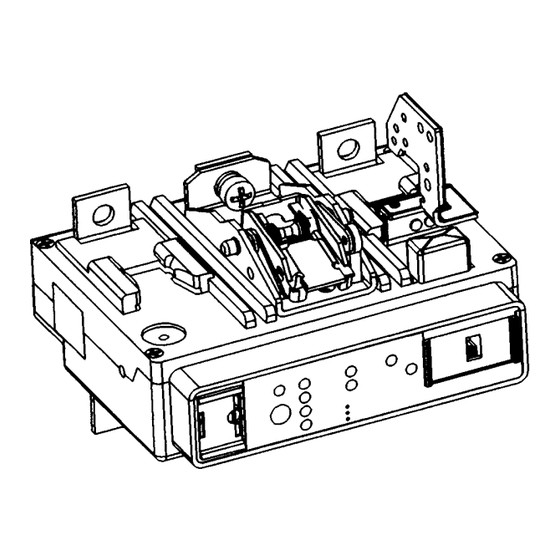
Figure 1-1 Digitrip OPTIM 550 Trip Unit for 3-Pole
K-Frame Series C Circuit Breaker
The recommendations and information contained herein
are based on Cutler-Hammer experience and judge-
ment, but should not be considered to be all-inclusive or
covering every application or circumstance which may
arise. If any questions arise, contact Cutler-Hammer for
further information or instructions.
1.0 GENERAL INFORMATION
The Digitrip OPTIM 550, illustrated in Figure 1-1, is an
electronic trip unit that incorporates a microprocessor-
based custom application specific integrated circuit
design for use with the Series C K-Frame Molded Case
Circuit Breakers.
The Digitrip OPTIM 550 provides true RMS current
sensing for proper correlation with thermal characteris-
tics of conductors and equipment. Interchangeable rat-
ing plugs are provided to establish the continuous cur-
rent rating of each circuit breaker.
I.L. 29C507
Advertisement
Table of Contents

Related Manuals for Eaton Digitrip OPTIM 550 KEP3125T52


Summary of Contents for Eaton Digitrip OPTIM 550 KEP3125T52
-
Page 1: Table Of Contents
Cutler-Hammer I.L. 29C507 Installation Instructions for the Digitrip OPTIM 550 3-Pole Trip Unit Installation and Operation with K-Frame Series C Circuit Breakers Table of Contents Description Page General Information ..... .1 UL Listed Devices . -
Page 2: Ul Listed Devices
I.L. 29C507 Page 2 The Digitrip OPTIM 550 Trip Unit is completely self con- Make sure that the trip unit is suitable for the intended tained and when the circuit breaker is closed, requires installation by comparing nameplate data with any exist- no external power to operate its protection systems. - Page 3 I.L. 29C507 Page 3 Ground fault trip units are supplied from the factory with a wire harness with pigtail lead connections for a neutral NOTICE current sensor (white and gray wires). A neutral current sensor is provided with each trip unit. Do not connect the neutral current sensor secondary Install the jumper plug assembly into the trip unit (see output to ground.
- Page 4 I.L. 29C507 Page 4 1.50 .281 Diam. .36R 2 Holes 6.17 1.438 1.47 .28R Ref. Polarity 4.375 Ref. Markings 5.61 5.75 2.188 .12R 2.25 2.33 3.04 Figure 3-3 Neutral Current Sensor Placement Table 3.1 Digitrip K-Frame OPTIM Rating Plugs Install circuit breaker covers and pan-head screws. Max Amps Catalog Number Install the rating plug into the trip unit (Figure 3-5 and...
-
Page 5: Principle Of Operation
I.L. 29C507 Page 5 4.0 PRINCIPLE OF OPERATION In open air at 40°C, a K-Frame circuit breaker with a Source Digitrip OPTIM 550 Trip Unit installed will carry continu- ously up to 400 amperes without exceeding a 50°C rise at the terminals. The calibration of the trip unit is insen- sitive to ambient temperatures over a range of -20°... -
Page 6: Testing
I.L. 29C507 Page 6 A "Thermal Memory" effect prevents the breaker from 5.2.3 GENERAL TEST INSTRUCTIONS being re-energized immediately after an overload. A "cooling off" period of up to 5 minutes is required, which The interconnected system shall be evaluated in accor- allows time for cabling to cool off. -
Page 7: Rating Plug
I.L. 29C507 Page 7 connections exactly as shown in Figure 5-3. The break- er should not trip and the ground fault alarm light should Voltage Source not light. Repeat the test using the other two combina- tions of breaker phases. Source CAUTION FIELD TESTING SHOULD BE USED FOR FUNCTION-... -
Page 8: References
I.L. 29C507 Page 8 7.0 REFERENCES Voltage Source 7.1 SERIES C K-FRAME MOLDED CASE CIRCUIT BREAKERS Source 29C104 Frame Instruction Leaflet AD 29-167K Typical Time-Current Characteristic curves for K-Frame Breakers 7.2 INTERNAL ACCESSORIES The following types of internal accessories, which mount on the trip unit, are available for use. - Page 9 I.L. 29C507 Page 9 GROUND FAULT TEST RECORD FORM Ground Fault Test Record should be Retained by Those in Charge of the Building’s Electrical Installation in order to be Available to the Authority having Jurisdiction Circuit Test Date Breaker Results Tested By: Number Figure 5-4 Typical Performance Test Record Form...
- Page 10 I.L. 29C507 Page 10 Cutler-Hammer Pittsburgh, Pennsylvania U.S.A. Effective 5/00 (ISI) Style 6602C55H01 Printed in U.S.A.
Need help?
Do you have a question about the Digitrip OPTIM 550 KEP3125T52 and is the answer not in the manual?
Questions and answers