Table of Contents

Related Manuals for Northern TVIVFBIR120


Summary of Contents for Northern TVIVFBIR120
-
Page 1: Users Manual
STARLIGHT Series Cameras For TVI Camera Models: TVIVFBIR120, TVIVFDIR120, TVITIR120, TVID212IR2 TVIVFBIR120 TVIVFDIR120 USERS MANUAL TVITIR120 TVID212IR2 ♦ ♦ 3625 Cincinnati Avenue, Rocklin, CA 95765 855-388-7422 www.northernvideo.com Rev. 021418... -
Page 2: Regulatory Information
User Manual Thank you for purchasing our product. If there are any questions, or requests, do not hesitate to contact technical support at 855-388-7422. This manual applies to HD 1080p Ultra Low-Light Cameras. This manual may contain several technically incorrect places or printing errors. - Page 3 1. This device may not cause harmful interference. 2. This device must accept any interference received, including interference that may cause undesired operation. EU Conformity Statement This product and - if applicable - the supplied accessories too are marked with "CE" and comply therefore with the applicable harmonized European standards listed under EMC Directive 2014/30/EU, the RoHS Directive 2011/65/EU.
- Page 4 Safety Instruction These instructions are intended to ensure that user can use the product correctly to avoid danger or property loss. The precaution measure is divided into “Warnings” and “Cautions” Warnings: Serious injury or death may occur if any of the warnings are neglected.
- Page 5 Make sure that the plug is firmly connected to the power socket. When the product is mounted on wall or ceiling, the device shall be firmly fixed. If smoke, odor or noise rise from the device, turn off the power ...
- Page 6 To avoid heat accumulation, good ventilation is required for operating environment. While in delivery, the camera shall be packed in its original packing, or packing with the same protection.
-
Page 7: Table Of Contents
1.1 Product Features ..............8 1.2 Overview of TVIVFDIR120 Outdoor Dome Camera ....9 1.3 Overview of TVID212IR2 Indoor Dome Camera .....10 1.4 Overview of TVIVFBIR120 Outdoor Bullet Camera ....10 1.5 Overview of TVITIR120 Outdoor Turret Camera ....11 Chapter 2 Installation 2.1 TVIVFDIR120/TVID212IR2 Installation ........12... - Page 8 3.3.9 ADJUST ................40 3.3.10 RESET ................41 3.3.11 EXIT ................41...
-
Page 9: Chapter 1 Introduction
Chapter 1 Introduction Product Features The camera is applicable for both indoor and outdoor conditions, and the application scenarios include road, warehouse, underground parking lot, bar, etc. The main features are as follows: High performance CMOS sensor 1080p resolution ... -
Page 10: Overview Of Tvivfdir120 Outdoor Dome Camera
Overview of TVIVFDIR120 Outdoor Dome Camera Bubble Alarm Cable Power ( 24 V AC/12 V DC) Menu Video Cable (TVI) Video Cable (CVBS) Button Auxiliary Video Output DIP Switch Back Box Figure 1. 1 Overview of TVIVFDIR120 Outdoor Dome Camera... -
Page 11: Overview Of Tvid212Ir2 Indoor Dome Camera
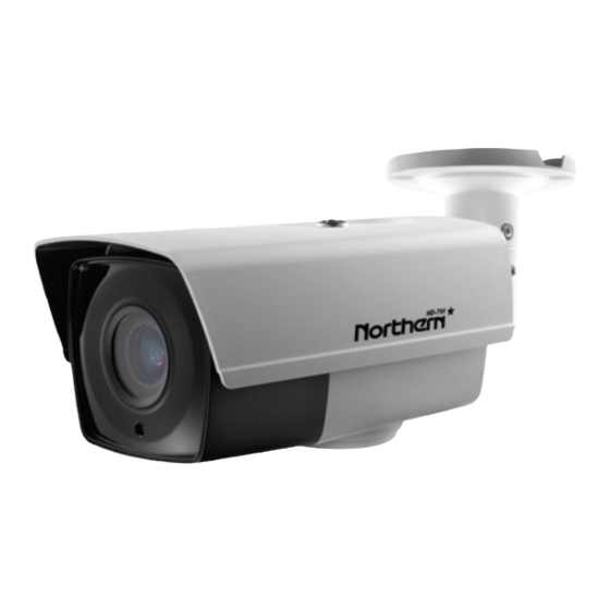
Figure 1. 2 Overview of TVID212IR2 Indoor Dome Camera Overview of TVIVFBIR120 Outdoor Bullet Camera Alarm Cable Bracket Power Cable ( 24 V AC/12 V DC ) Main Video Cable (TVI) Body Video Cable (CVBS) Lens Figure 1. 3 Overview of TVIVFBIR120 Outdoor Bullet Camera... -
Page 12: Overview Of Tvitir120 Outdoor Turret Camera
Overview of TVITIR120 Outdoor Turret Camera Mounting Base Trim Ring Enclosure Camera Figure 1. 4 Overview of TVITIR120 Outdoor Turret Camera... -
Page 13: Chapter 2 Installation
Chapter 2 Installation Before you start: Make sure that the device in the package is in good condition and all the assembly parts are included. Make sure that all the related equipment is power-off during the installation. Check the specification of the products for the installation environment. - Page 14 Note: Cable hole is required when you adopts ceiling outlet to route the cables. TVIVFDIR120 TVID212IR2 Type II Camera: Type I Camera: Figure 2. 1 The Drill Template 3. Loosen the screws on the bubble of the dome camera to remove the bubble and the black liner.
- Page 15 Note: In the supplied screw package, both self-tapping screws and expansion blots are contained. If the wall is cement, expansion blots are required to fix the camera. If the wall is wooden, self-tapping screws are required. 5. Route the cables through the cable hole or the side opening. 6.
-
Page 16: In-Ceiling Mounting
TVIVFDIR120 TVID212IR2 Type II Camera: Type I Camera: 0° to 75° 0° to 355° 0° to 340° 0° to 75° 0° to 355° 0° to 355° Figure 2. 4 3-Axis Adjustment 9. Fit the black liner on the camera and tighten the screws on the bubble of the dome camera to finish the installation. - Page 17 4. Push the two toggles through the two screw holes in the ceiling. Rotate the bolt till the toggle holds the ceiling tightly. Figure 2. 5 Install the In-Ceiling Mounting Bracket 5. Route the cables through the cable hole. 6. Attach the back box of type I camera/base plate of type II camera to the in-ceiling mounting bracket with the supplied screws.
-
Page 18: Tvivfbir120 Camera Installation
Figure 2. 6 Fix the Camera to the Mount 7. Repeat steps 6 to 9 of the 2.1.1 Ceiling Mounting section to complete the installation. 2.2 TVIVFBIR120 Camera Installation 2.2.1 Ceiling Mounting Note: Both wall mounting and ceiling mounting are suitable for the bullet camera. - Page 19 2. Drill the screw holes and cable hole (optional) on the ceiling according to the supplied drill template. Note: Cable hole is required when adopting ceiling outlet to route the cable. TVIVFBIR120 Type III Camera Screw Hole 120° 120° Figure 2. 7 The Drill Template 3.
- Page 20 TVIVFBIR120 Type III Camera Figure 2. 8 Fix the Camera to the Ceiling 8. Connect the corresponding cables, such as power cable, and video cable Note: In the supplied screw package, both self-tapping screws and expansion blots are contained.
- Page 21 Auxiliary Video Output Menu Button DIP Switch Figure 2. 9 Internal Interface and Button 9. Power on the camera to check whether the image on the monitor is gotten from the optimum angle. If not, adjust the surveillance angle. 1) Loosen the No.1 adjusting screw to adjust the pan position [0°...
-
Page 22: Mounting With Junction Box
Figure 2. 10 3-Axis Adjustment 2.2.2 Mounting with Junction Box Note: You need to purchase a junction box separately if you adopt the mounting with a junction box. Steps: 1. Attach the drill template on the wall/ceiling. 2. Drill screw holes and the cable hole in the wall/ceiling according to the holes of the drill template. -
Page 23: Tvitir120 Camera Installation
6. Secure the camera with M4 × 10 screws on the junction box. TVIVFBIR120 Type III Camera Figure 2. 12 Wall/Ceiling Mounting with the Junction Box 7. Repeat steps 5 to 6 of the 2.2.1 Ceiling Mounting to install the camera to complete the installation. - Page 24 2. Attach the drill template (supplied) to the place where you want to install the camera, and then drill the screw holes and the cable hole (optional) on the ceiling according to the drill template. The cable can also be routed through the side. Use pliers to remove the plastic tab if routing cables through side outlet on trim ring.
- Page 25 If the wall is cement, expansion blots are required to fix the camera. If the wall is wooden, self-tapping screws are required. Figure 2. 15 Secure the camera to the Ceiling 5. Adjust the viewing angle of the camera. 1).
- Page 26 Figure 2. 17 Adjust the viewing angle Figure 2. 18 Install the Trim Ring Figure 2. 19 Complete the Installation...
-
Page 27: Chapter 3 Menu Operation
Call the menu by pressing the joystick button (TVIVFBIR120/TVIVFDIR120/TVID212IR2 only) b) Call the menu with supported DVR/TVI DVR by clicking button on the PTZ interface, or by calling preset No. 95. - Page 28 SMART FOCUS INDOOR OUTDOOR SCENE VIDEO OUT INDOOR1 LOW-LIGHT MANUAL LENS SHUTTER EXPOSURE SENS-UP BRIGHTNESS SET UP D-WDR DEFOG BACKLIGHT WHITE BAL LANGUAGE AWC-SET MANUAL COLOR DAY & NIGHT AUTO 2D NR 3D NR CAM TITLE SPECIAL D-EFFECT MOTION PRIVACY DEFECT VOLTAGE DET.
-
Page 29: Video Out
Note: TVITIR120 does not support SMART FOCUS. 3.1 VIDEO OUT PAL: (Phase Alternating Lines) is a color encoding system for analog television used in broadcast television systems in most countries. NTSC: (National Television System Committee) is the analog television system that is used in most of North America, parts of South America, Myanmar, South Korea, etc. -
Page 30: Scene
SMART FOCUS available on TVIVFBIR120 TVIVFDIR120 and TVID212IR2 models only. Adjusting the lens when using the 960H output requires pressing the joystick to call the menu, then entering Smart Focus. Press the joystick up and down to Zoom in or Out. -
Page 31: Exposure
3.3.4 EXPOSURE Exposure describes the brightness-related parameters. You can adjust the image brightness by the SHUTTER, AGC, SENS-UP, BRIGHTNESS, and D-WDR in different light conditions. EXPOSURE 1. SHUTTER AUTO 2. AGC 3. SENS-UP 4. BRIGHTNESS ---|------ 40 5. D-WDR 6. DEFOG 7. - Page 32 AGC: It’s a form of amplification where the camera will automatically boost the image output signal to optimize the clarity of image in poor light conditions. You can set the AGC value from 0 to 15. The AGC is disabled if the value is set to 0. Note: The noise will be amplified if the AGC is on.
-
Page 33: Backlight
DEFOG: DEFOG is used in special environment such as the foggy or rainy weather or in high illumination, in which the dynamic range is lower than that in the ordinary environment and the image always appear hazy. Enable the defog function can enhance the subtle details so that the image appears clearer. - Page 34 GAIN: The gain of BLC can be set as High, Middle, or Low, the higher the gain, and the clearer the image is. AREA: Click the up/down/left/right button to define the BLC position and size. Select RET to go back to the BLC menu or re-define the BLC area.
- Page 35 OSD menu. If this occurs you need to flip the internal switch located next to the video test output on the TVIVFBIR120, TVIVFDIR120, and TVID212IR2 models. The TVITIR120 does not include a joystick for OSD – in order to turn WDR off on the TVITIR120 when in 960 model you will need to connect the two bare lead wires on the cable harness –...
-
Page 36: White Balance
WDR OFFSET: You can set the value from 0 to 60.The higher the value, the vaguer the image is. 1. GAIN MIDDLE 2. WDR BRIGHT --|------ 38 3. WDR OFFSET |--------- 0 4. RETURN Figure 3. 7 WDR 3.3.6 WHITE BALANCE White balance is the white rendition function of the camera to adjust the color temperature according to the environment. -
Page 37: Day & Night
AWC→SET to get another proper white balance for the new scene. 3.3.7 DAY & NIGHT Color, B/W, and AUTO are selectable for DAY & NIGHT switch. COLOR: the image is colored in day mode all the time. B/W: the image is black and white all the time, and the IR LED turns on in the low-light conditions. - Page 38 SPECIAL 1. CAM TITLE 2. D-EFFECT 3. MOTION 4. PRIVACY 5. DEFECT 6. VOLTAGE DETECION 7. RETURN Figure 3. 8 Special MOTION: In the user-defined motion detection surveillance area, the moving object can be detected and the alarm will be triggered.
- Page 39 Figure 3. 9 Motion PRIVACY: The privacy mask allows you to cover certain areas which you don’t want to be viewed or recorded. Up to 8 privacy areas are configurable. PRIVACY 1. SELECT AREA 1 2. DISPLAY MOSAIC 3. COLOR 4.
- Page 40 sense light levels correctly. This series of camera supports defective pixel correction. Move the cursor to DEFECT and click Iris+ to enter the defective pixel correction interface. LIVE DPC, and STATIC DPC are adjustable in this section. DEFECT 1. LIVE DPC ...
- Page 41 3.3.9 ADJUST In the Adjust sub-menu, you can configure the settings, including the sharpness, the image quality on monitor, and the LSC (lens shading compensation). Move the cursor to ADJUST and click Iris + to enter the adjust configuration interface. ADJUST --------|15 1.
- Page 42 Gamma is the name of a nonlinear operation used to code and decode luminance or tristimulus values in video or still image system. LSC: Lens shading correction corrects the phenomenon that the image gets darkened or blurred on the periphery. Set it as ON, move the cursor to SCAN and click Iris+ to correct the lens shading.
Need help?
Do you have a question about the TVIVFBIR120 and is the answer not in the manual?
Questions and answers