Advertisement
Quick Links
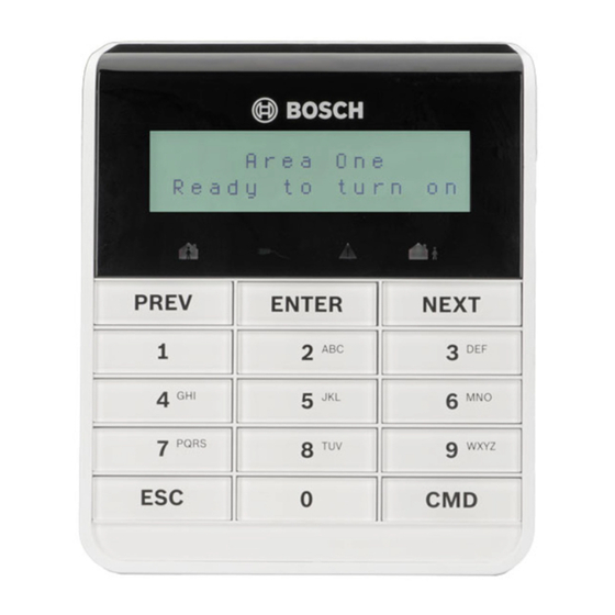
1 | Overview
The B915 and B915I keypads are SDI2 bus devices.
The B915 function keys are labeled in English. The B915I
function keys are labeled with icons.
1
2
R
Y
G
B
COM Z1
PWR A
B COM
3
ON
DIP
1
2
3
4
5
6
Callout ― Description
1 ― Tamper switch
2 ― SDI2 wiring terminal block
3 ― Address switches
2 | SDI2 address switches
Address switches set the address for the keypad. The control
panel uses the address for communications. To set the
switches, use a ballpoint pen.
2.1 | Accessing the address switches
1.
Insert a slotted screwdriver under the mounting plate
(callout #1). Do not pry upwards.
2.
To release the mounting plate, push the plate towards
the bottom of the keypad.
3.
Remove the plate. Refer to the following illustration.
2
1
Callout ― Description
1 ― Retention clip
2 ― Mounting plate
2.2 | Setting the keypad address
To set the keypad addresses (per the control panel
configuration), use the DIP switches. If multiple SDI2
keypads are on the same system, each keypad must have a
unique address. The following illustration shows the address
switch setting for address 01. Refer to the table for keypad
address settings for address 00 to 32.
ON
DIP
1
2
3
4
5
6
DIP Switches ON
DIP Switches ON
1
2
3
4
5
6
1
2
3
4
5
00
17
X
X
01
X
18
X
X
02
X
19
X
X
X
X
X
X
X
03
20
04
X
21
X
X
X
05
X
X
22
X
X
X
X
X
X
X
X
X
06
23
07
X
X
X
24
X
X
08
X
25
X
X
X
09
X
X
26
X
X
X
10
X
X
27
X
X
X
X
11
X
X
X
28
X
X
X
12
X
X
29
X
X
X
X
13
X
X
X
30
X
X
X
X
14
X
X
X
31
X
X
X
X
X
X
X
X
X
15
32
16
X
3 | Installing
CAUTION!
Remove all power (AC and battery) before making
any connections. Failure to do so might result in
personal injury and/or equipment damage.
3.1 | Installing the mounting plate
1.
Use the mounting plate to mark screw locations and wire
opening.
2.
Pull the wiring through the wire opening.
3.
Use the mounting hardware to attach to the wall.
6
3.2 | Installing the tamper screw
To provide tamper protection, install a screw into the tamper
location shown above.
X
3.3 | Wiring the keypad
1.
Connect the wiring to keypad terminals labeled R, Y, G, B.
2.
Attach the keypad to the mounting plate.
3.4 | Wiring to the control panel
Attach the wire to the control panel using terminals labeled R,
Y, G, B (PWR, A, B, COM). Refer to the following illustration.
B5512 control panel shown.
R Y G B
Open
3.7 - 5.0 VDC
1
Normal
2.0 - 3.0 VDC
Short
0.0 - 13 VDC
1 k
End of Line Resistors
AUX
1 COM 2
3 COM 4
5 COM 6
- 12 V +
3
COM AUX
R
Y
G
B
1
COM
2
3
COM
PWR A
B COM
R Y G B
R
Y
G
B
2
PWR A
B COM
Callout ― Description
1 ― Control panel
2 ― Terminal wiring
3 ― Keypad's wiring terminal block
Use the control panel terminals labeled R, Y, G, B (PWR, A, B,
COM). Connect them to the keypad terminals labeled R, Y, G, B.
Keypads can be wired directly to the control panel or from
keypad to keypad
R
Y
G B
Open
3.7 - 5.0 VDC
Normal
2.0 - 3.0 VDC
Short
0.0 - 13 VDC
1 k
End of Line Resistors
AUX
- 12 V +
1 COM 2
3 COM 4
5 COM 6
COM AUX
R
Y
G
B
1
COM
2
3
COM
PWR A
B COM
3.5 | Attaching the keypad
1.
Align the mounting hook openings over the mounting
hooks
2.
Push the keyboard down.
3.
Send power to the system.
4.
Test for proper operation.
Advertisement

Related Manuals for Bosch B915


Summary of Contents for Bosch B915
- Page 1 To set the keypad addresses (per the control panel CAUTION! The B915 function keys are labeled in English. The B915I Y, G, B (PWR, A, B, COM). Refer to the following illustration. configuration), use the DIP switches. If multiple SDI2 Remove all power (AC and battery) before making B5512 control panel shown.
- Page 2 When an area is in fire alarm, the keypad B6512 Copyright emits a pulsed, high-pitched bell tone. This document is the intellectual property of Bosch Security B5512 version 2.03 and higher B4512 version 2.03 and higher Systems, Inc. and is protected by copyright. All rights reserved.
Need help?
Do you have a question about the B915 and is the answer not in the manual?
Questions and answers