Table of Contents
Advertisement
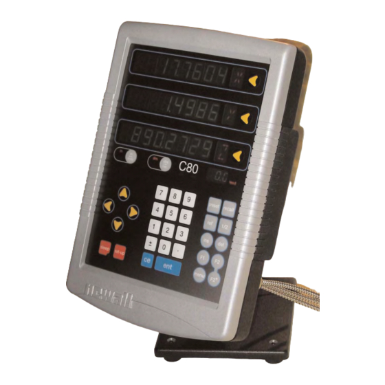
C80
Three Axis Digital Readout System
CONTENTS
2
3
4
4
4
5
5
6
6
6
7
7
7
7
8
8
9
9
10
10
10
11
12
Linear Error Compensation
13
Zero Approach
13
Axis Summing
13
Taper Display Axis
14
Add / Delete Function
14
Reset
14
Store
15
SPECIAL FUNCTIONS
15
Menu Function
16
16
18
Arc Contouring
20
Line Hole
22
Polar Coordinates
23
23
Taper
24
Tool Offsets
26
27
28
GENERIC FUNCTIONS
31
31
Advertisement
Table of Contents

Subscribe to Our Youtube Channel
Related Manuals for Newall C80


Summary of Contents for Newall C80
-
Page 1: Table Of Contents
NEWALL MEASUREMENT SYSTEMS Three Axis Digital Readout System CONTENTS SPECIFICATIONS CONNECTIONS MOUNTING Arm Mounting (Non-adjustable) Arm Mounting (Adjustable) Face Mounting (Adjustable) Lathe Mounting (Adjustable) OPERATION Understanding the Displays Using the Keypad STANDARD FUNCTIONS Setting the Datum for Each Axis Using Digifind... -
Page 2: Newall Measurement Systems
Relative Humidity Maximum 80% for temperatures up to 31°C decreasing linearly to 33% at 45°C Disposal At the end of its life, the C80 system should be disposed of in a safe manner applicable to electronic goods. DO NOT BURN. -
Page 3: Connections
• Turn off the power before connecting the encoder, by disconnecting the power supply connector. • Ensure that the C80 is grounded to the machine before turning on the machine supply. DO NOT CONNECT THIS UNIT DIRECTLY TO THE MAINS SUPPLY. -
Page 4: Mounting
MOUNTING, Arm mounting C80 Three Axis Digital Readout System MOUNTING NOTES • The C80 can be mounted in a variety of ways, depending on the mounting assemblies purchased with the unit: Arm Mounting (Non-adjustable) Mounting arm assembly Part no. 294-35670 M10 stud &... -
Page 5: Face Mounting (Adjustable)
MOUNTING, Face Mounting, Lathe mounting C80 Three Axis Digital Readout System NOTES Face Mounting (Adjustable) Face mount adjustable pivot assembly Part no. 600-80270 Lathe Mounting (Adjustable) Lathe mount adjustable pivot assembly Part no. 600-80280 Lathe carriage assembly Part no. 600-80280 Lathe headstock mount assembly Part no. -
Page 6: Operation
In this mode, the C80 will display the positions of the three axes relative to a fixed datum. Incremental Mode • In this mode, the C80 can be used to display each position relative to the last position. This is also At the beginning of each working session, set the known as point-to-point use. -
Page 7: Standard Functions
STANDARD FUNCTIONS, Setting the Datum, Digifind, Centerfind C80 Three Axis Digital Readout System STANDARD FUNCTIONS NOTES Setting the Datum for Each Axis Zero Using Zero redefines the • To zero one display at the current position: datum, so it will not be Press the Select Key for the axis to be zeroed. -
Page 8: Setup
SETUP , Using Setup Mode C80 Three Axis Digital Readout System SETUP NOTES Using Setup Mode Normally, Setup needs to • To enter Setup Mode, first exit from any Special Function that is running, then press be done only once, and it... -
Page 9: Machine Type
SETUP , Machine Type, Encoder C80 Three Axis Digital Readout System Machine Type NOTES This setting allows you to choose whether the special functions for Mill or Lathe are available. There are three possible settings: Generic Mode all functions available... -
Page 10: Radius / Diameter
Direction The Direction setting allows you to match the C80 to the actual direction of travel of any axis. There are two possible settings for each axis: The Direction setting is quite arbitrary. -
Page 11: Segmented Error Compensation
Enter the distance from the Starting Point, as measured by the standard. For Example: Press to enter a Correction Point of 678.9. The C80 will calculate and display the correction factor for this point. will Pressing clear •... -
Page 12: Mill Functions
MILL FUNCTIONS, Bolt Hole Circle C80 Three Axis Digital Readout System MILL FUNCTIONS NOTES The Functions described here are available when the C80 is in Mill Mode, and also when in Generic Mode. Bolt Hole Circle This function is also known as Pitch Circle Diameter. - Page 13 MILL FUNCTIONS, Bolt Hole Circle C80 Three Axis Digital Readout System NOTES Bolt Hole Circle continued • The function display shows , and the top axis display shows the Circle Diameter. Enter a new value if required. For Example: Press Press to move to the next step.
-
Page 14: Lathe Functions
LATHE FUNCTIONS, Summing C80 Three Axis Digital Readout System Axis Summing NOTES This function allows the movement of the Z’ axis to be added to the movement of either the X axis or the Z axis. The conventional way to The Summing Function is useful when the compound is set to align with either of those two axes. -
Page 15: Vectoring
LATHE FUNCTIONS, Vectoring C80 Three Axis Digital Readout System Vectoring NOTES This function allows the movement of the X and Z axes to be combined with the angle of the compound. This function is available only on 3-axis units. The conventional way to The Vectoring Function is useful when the compound is set at an angle. -
Page 16: Troubleshooting
• If you have a Spherosyn scale, check that the scale is not bent, by removing it and rolling it on a flat surface. If the solutions suggested above do not solve your problem, contact Newall for further instruction. CLEANING •...
Need help?
Do you have a question about the C80 and is the answer not in the manual?
Questions and answers