Table of Contents
Advertisement
Quick Links
Advertisement
Table of Contents

Subscribe to Our Youtube Channel
Related Manuals for Newall NMS 100


Summary of Contents for Newall NMS 100
- Page 1 NMS 100 Digital Readout User Manual...
-
Page 2: Table Of Contents
Contents Specification Page 3 Trouble Shooting Page 30 Electrical Page 3 Physical Page 3 Environment Page 3 Accreditation Page 3 Disposal Page 3 Input and Resolution Page 3 Mounting Options Page 4 Stand Alone Page 4 Panel Mount Page 4 Connection Details Page 5 Important Information... -
Page 3: Specification
Dependant on Encoder (Linear) Dependant on Encoder (Rotary) 0.1µm (0.00001”) Program PPR, 0 - 90,000,000 0.5µm (0.00002”) 1µm (0.00005”) 2µm (0.0001”) 5μm (0.0002”) 10μm (0.0005”) Newall Measurement Systems Limited reserves the right to make changes to this specification without notice... -
Page 4: Mounting Options
NMS100 MOUNTING DETAILS STATED: - DIMENSIONS ARE SHEET DRAWING DRAWN THIS DRAWING IS THE PROPERTY OF Chris.Wh NEWALL MEASUREMENT SYSTEMS LTD. 1 OF 1 THE INFORMATION THERON MAY NOT BE COPIED OR USED REV.ISS. DATE C.N.No ALTERATION DATE 07/03/2018 England NUMBER... -
Page 5: Connection Details
Connection details Important Details The NMS100 is only compatible with TTL Encoders. It is important to ensure that: Secure all the cables to prevent the connectors from dropping into hazardous positions (for example the floor or coolant tray) when they are unplugged. Route all cables to prevent them from being caught on moving parts. -
Page 6: Encoder Connections
Connection details Encoder Connections The Axis connectors consist of a 9 way “D” - Type connectors with the following pin assignment for both single ended and deferential connection, this is depended on the NMS100 digital model. *Single ended will require and additional dongle for use*... -
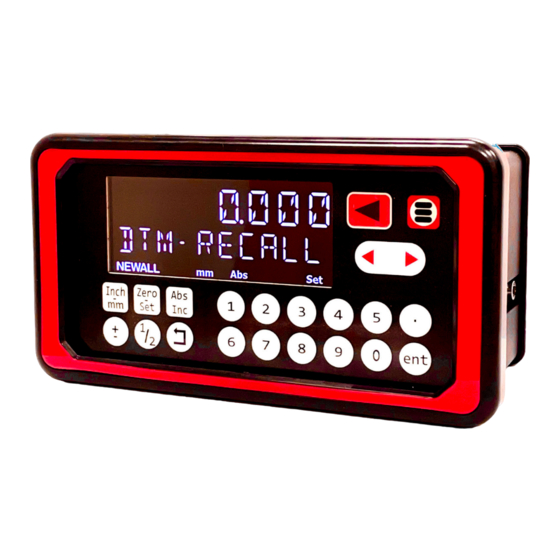
Page 7: Display And Keypad
Display and keypad Understanding The Display 0. 0 00 Axis 1 Scrolling Message DTM-recall display Newall mm/inch ABS/INC Zero/Set Short cut Short cut Short cut Understanding The Keypad Switches between zero Axis selection key and axis pre-set modes Switches between absolute... -
Page 8: Setting Up The Unit (Linear)
Setting up the unit (Linear) Navigating Setup (Linear) How to enter setup DRO setup code setup- Language EnG Gb espanol Francais dansk deutsch cesky italiano polski setup- encoder TYPE linear rotary 0. 0 05 setup- encoder res 0. 0 01 0. -
Page 9: Navigating Setup (Rotary)
Navigating Setup (Rotary) When changing your NMS 100 encoder type from Linear to Rotary, some menu options will change to match your rotary encoder. Below are the changes between rotary and linear. -
Page 10: Language Setup
Setting up the unit (Linear) Language Setup This setting enables the user to choose the language that is required to be displayed in the NMS100 display. There are language settings: English UK (Default) EnG Gb English US Italian Czech italiano cesky French Polish... -
Page 11: Display Resolution Setup (Linear)
Setting up the unit (Linear) Display Resolution Setup (Linear) The display resolution settings available for each axis can not be finer than the encoder resolution. The inch/mm setting will also define the resolution that is actually displayed as per the below table: Display µ... -
Page 12: Feed Rate Display Setup
Measurement display feed- 00. 0 Feed rate display Newall Press the axis select key next to the axis to cycle through the options When the feed rate is active it will be displayed in the number display, see example below... -
Page 13: Beep / Tone Setup
Setting up the unit (Linear) Beep / Tone Setup This setting enables or disables an audible tone coming from the unit when a button is pressed. The default setting is on Press the axis select key next to the axis to cycle through the options Once turned off no audible tone will be made Error Compensation The digital readout (DRO) system helps to improve productivity. -
Page 14: Error Compensation
Setting up the unit (Linear) Error Compensation Continued To evaluate machine errors: C80 user guide.book Page 5 Thursday, October 2, 2008 7:48 AM 1. Put the laser target / dial indicator on the part of the machine where the machining is done. Error compen 2. -
Page 15: Linear Error Compensation Setup
0, where no compensation is being applied. Compensation value currently applied Setup - Linear Newall Press the axis select key next to the axis to cycle through the options Teach mode, compares physical movement with actual measurement... - Page 16 Setting up the unit (Linear) Teach Mode Continued 1000. 0 00 Move your encoder to you end position (end point) tch - Press the to accept the end point tch - movement enter the actual measurement using the numeric keypad 1000.
- Page 17 Correction factor = (500.000 - 500.200) / 500.000 x 1,000,000 Correction factor = -400 PPM To enter this value into the display: program Press the key to enter the program mode prg - Newall enter the correction factor using the numeric keypad -400 prg - editing Newall Press the...
-
Page 18: Scaling Setup
The scaling setup function allows a constant factor to be applied to the measurement, this can be useful for using the display for indirect measurement purposes. 1. 0 00 the default value is 1.000, (normal measurement) setup - scaling Newall Press the key to enter the scaling edit mode scaling - edit Newall enter the desired scaling factor using the numeric keypad In the example below a factor of 2.5 is being applied... -
Page 19: Sleep Setup
Signal Check setup (continued) When this setting is enabled, the NMS 100 will check for the different signals required. If the signal retrieved is an illegal signal, the DRO will return with SIG FAIL as shown in the table below. If a signal comes back and is correct, the DRO will continue as normal. -
Page 20: Reset Setup
WARNING:: Enabling this setting will erase any data that was previously stored in the functions and settings of the readout. setup - reset Newall Press the axis select key next to the axis to cycle through the options setup -... -
Page 21: Setting Up The Unit (Rotary)
There are two ways to set this resolution of your rotary encoder, they are “teach” and “program”. To scroll through the settings press the key. CPR Teach Setup teach setup - Newall Press the key to enable teach. tch - rotate axis Newall Turn you encoder for one revolution. -
Page 22: Degrees Setup
Setting up the unit (Rotary) CPR Program Setup (continued) prg - Newall Using the numerical keypad on the NMS100, enter the resolution of your rotary encoder. NOTE: when inputting your resolution, multiply your resolution by 4 7200 prg - accept... -
Page 23: Rollover Setup
To change between these two modes, navigate to the “Rollover” setup and press the key. 359 . 999 0. 0 00 Newall Newall As the unit approaches 360, it will stop and 359.999 and keep counting from 0 in Rollover mode. 643 . 000 Newall the display above shows the unit in continuous mode. -
Page 24: Feed Rate Setup
00. 0 Feed rate display Newall Gearing Setup The Gearing setup allows you to scale your rotary encoder to any equipment in-between your encoder and your end product. The NMS100 is set to a 1:1 ratio at factor settings. -
Page 25: Standard Functions
Newall Press the axis select key next to the axis to cycle through the options zero approach Enable or disable the zero approach function, (the default is disabled). -
Page 26: Digital Readout Information
How to enter DRO Info DRO info v 1. 0 0 Software Version - - - - - - - - Unit Serial Number Newall t t l / q u a d Digital Readout Type (Dependant on model purchased) type Newall... -
Page 27: Inch / Mm
Standard functions Inch and mm Modes Press to toggle between Inch and mm measurement modes. Metric (mm) mode has been selected The NMS100 has a dedicated key to switch the positional displays between imperial (inch) and metric (mm) measurements. The current display mode is indicated at the bottom left of the screen as shown right. -
Page 28: Zero Approach Function
0 . 0 0 0 Encoder position display DTM-recall Newall Zero Approach Tolerance The zero approach tolerance setting defines the accuracy of when the visual indication is at zero. For ex- ample if the setting was 0.01mm, the visual indication will be full (at zero) when at or passed 0.01mm... -
Page 29: Zero Approach Maximum
Zero Approach Maximum tolerance Press the axis select key next to the axis to cycle to the next option. zero approach Newall M a x i m u m Press the key to set the zero approach tolerance zero approach Newall 1 . -
Page 30: Fraction Function
0 . 2 5 0 0 Encoder position display Fraction display + Newall Setpoints Function The NMS100 can store up to 50 Setpoint positions, or machining steps into the memory. Using setpoints allows the operator to work to zero by calling up stored dimensions, instead of “working up” to drawing dimensions. This eliminates the need to constantly refer to the drawing, and reduces the possibility of scrapping parts due to misread dimensions. - Page 31 Newall enter the dimension required via the keypad for the first set point 1 5 0 . 0 0 0 program...
- Page 32 Newall to return to the function menu, or to exit functions and return to measurement display with setpoints active 1 0 0 . 0 0 0...
-
Page 33: Logging Function
The NMS100 readout is capable of offering basic serial communications via a dedicated hardware RS232 compatible port, This is only used for output purposes and is how the logging function operates. The communication parameters for the NMS 100 are: 115200 band, no parity, 1 stop bit, 8 data bit. Logging Connection (RS232) On the back of the NMS100 is a 15 way D female connector that is used to allow logging data to be output to another compatible RS232 device. -
Page 34: Rs232 Output Data Format
Standard functions RS232 Output Data Format The output data for the RS232 is as follows; The current axis data for the axes available on the system in transmitted. For two axes systems, only two axes of data will be transmitted. The data Packet structures of 12 characters is defined as follows: The Axes ID is the representation of the axis at the time of printing. - Page 35 • If a Spherosyn scale is in use, check that the scale is not bent, by removing it and rolling it on a flat surface. If the solutions suggested above do not solve the problem, contact Newall for further instruction. To swap encoders to trace a fault: 1.
- Page 36 Fax: +44 (0) 116 264 2731 E-mail: sales@newall.co.uk Web: www.newall.co.uk AMERICAS Newall Electronics Inc. 1803 O’Brien St. Columbus, Ohio 43228 USA Tel: +1 614 771 0213 Fax: +1 614 771 0219 More information at sales@newall.com • www.newall.com Document number: 023-82595...
Need help?
Do you have a question about the NMS 100 and is the answer not in the manual?
Questions and answers