Table of Contents
Advertisement
Quick Links
Advertisement
Table of Contents

Related Manuals for Newall C80


Summary of Contents for Newall C80
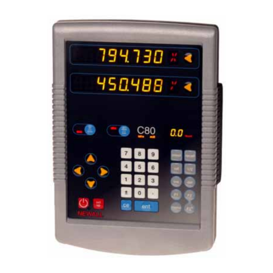
- Page 1 C80 Digital Readout System Instruction Manual Newall Measurement Systems Ltd...
- Page 2 Notes...
- Page 4 Display Keypad Axis Label Numeric Mode Key Units Key Displays Keypad Axis Navigation Function Axis Select Keys Keys Displays Keys Function Display Sleep Key Enter Setup Key Clear Entry (Store Changes)
-
Page 5: Table Of Contents
Contents Specifications ......1-1 Axis summing ......5-12 Electrical . - Page 6 Generic functions ......10-1 Sub-datums ....... 10-1 Jobs.
-
Page 7: Specifications
Specifications Depth Specifications This chapter details the specifications for the C80. (not including connectors) Electrical 50mm (1.97”) EMC compliance Weight BS EN 61000-6-4:2001 2.9kg (6.38lb) BS EN 61000-6-2:2001 Environmental Power supply unit (supplied) Operating temperature 100 – 240V (47 – 63Hz) 0 to 45°C... -
Page 8: Input
Specifications Disposal Resolutions At the end of its life, you should dispose of the C80 system in a Spherosyn or Microsyn 10 safe manner applicable to electronic goods. (menu selection) Do not burn. The casework is suitable for recycling. Please consult local 5µm (0.0002”) -
Page 9: Connections
Connections Connections This chapter shows the cable connections for the C80. Cable connections Power Indicator Lamp 2.5mm Power Inlet 15 Vdc ±10% @1A Encoder Inputs 9-way ‘D’ (All plugs should be Equipotential Terminal screwed finger tight) (Should be grounded to... - Page 10 Connections You can only use the C80 with Newall Spherosyn and Microsyn analogue encoders. You need to ensure that: • You secure all the cables to prevent the connectors from dropping into hazardous positions (for example the floor or coolant tray) when you unplug them.
-
Page 11: Mountings
Mountings This chapter shows the various options for mounting the C80. Arm Mount Adjustable Pivot You can mount the C80 in a variety of ways. The one that you Assembly use depends on the mounting assemblies that you purchased Part no. 600-80290... -
Page 12: Lathe Mounting (Adjustable)
Mountings Lathe mounting (adjustable) Lathe mounting (adjustable) with arm assembly Lathe Mount Adjustable Pivot Assembly Arm Mount Adjustable Pivot Part no. 600-80280 Assembly Part no. 600-80290 Lathe Carriage Assembly Lathe Carriage Mount with Part no. 294-61695 Arm Assembly UK part no. 600-80310 US part no. -
Page 13: Display And Keypad
Lathe Mode X, Z and Z’). Absolute mode Function display In this mode, the C80 displays the positions of the three axes While any axis is moving, the Function display shows the relative to a fixed datum. Feedrate of the fastest moving axis. The feed indicator next to the display is illuminated. - Page 14 Display and keypad Sleep mode Press the [Sleep Key] to temporarily turn off the displays and the keypad. While the unit is in Sleep Mode, all the settings are preserved, but the positions of the three axes are updated. If you move any of the axes while in Sleep Mode, the centre display shows ‘diSPLACd’.
-
Page 15: Set Up
Linear Compensation see note below Setup mode Segmented see note below Normally, you only need to set up the C80 once. You may find Compensation that the factory default settings are suitable so you do not need Addition to change them. -
Page 16: Machine Type
The Encoder settings must match the actual encoder in use, When you have finished setting all the options: or the C80 will not display correctly. Press the down navigation key until ‘StorE’ appears in Encoder type the middle display. -
Page 17: Radius / Diameter
Radius / diameter Direction Microsyn Microsyn Display Spherosyn You use the Direction setting to match the C80 to the actual direction of travel of any axis. µm There are two settings for each axis: ‘dir. 0’ and ‘dir. 1’. 0.005 0.0002 Press the Select Key next to the ‘X’, ‘Y’... - Page 18 Place the target of the laser or the needle of the dial Make a series of movements and compare the position indicator directly on the Newall reader head. readings between the laser / dial indicator and the DRO It is absolutely critical that you take the readings directly display.
- Page 19 Error compensation Way errors There are three settings for each axis: Err OFF Axis SEG Err Segmented Compensation Typical Yaw Deviation Lin Err Linear Compensation Straightness Press the Select Key next to the ‘X’, ‘Y’ or ‘z’ to cycle through Roll Axis these settings.
- Page 20 When you apply power, the display for any axis that is set to use Starting point - zero Segmented Compensation shows ‘rESEt’. Error If the machine has not been moved since the power was turned off, press [ce], and the C80 restores the last positions that were Travel recorded. Correction points Reference point Alternatively, you can set each axis close to the Reference Point, to within: 6.3mm (0.25”) for a Spherosyn encoder or...
- Page 21 Compensation to On, the data is re-applied. Correction Point of 678.9. You must carry out this procedure in strict sequence, and in full, The C80 calculates and displays the correction factor for for it to be valid. this point. You can press the Select Key at steps 1 to 8 to display the Press the down navigation key to go to the next point.
- Page 22 For this example you need to increase the value displayed on a stepped standard, and approach each edge from the same the C80 to match the standard, as this is a positive correction direction; or if you must approach each edge from opposite factor.
-
Page 23: Rs232 Options
RS232 options Setting the correction factor RS232 options RS232 was added as a standard feature to the C80 in March To set the correction factor: 2005. Set one or more axes to Linear Error Compensation as The C80 DRO can offer basic RS232 communications via a described in Error compensation on page 5-3. -
Page 24: System Settings
Connections return character You connect the RS232 to the C80 via a 15-pin D-type connector at the rear of the display. The Axis ID is the character shown in the axis 15-segment display at the time of printing. The exception is that for three- axis Lathe applications a lower case ‘z’... -
Page 25: Axis Summing
Axis summing All other connections are reserved and should be left Baud Rate Maximum Serial Rate (s) unconnected or the unit may be damaged. 14400 Operation 19200 You configure the RS232 output from the setup menu, using the 38400 following settings: ‘bd rAtE’... -
Page 26: Zero Approach
Set up Zero approach Press the down navigation key. The displays for the selected axes change to ‘0000’ or a This flashes the Axis Label display when one or more axes are previously entered value. approaching zero. Press the Select Key next to the ‘X’, ‘Y’ or ‘z’ to choose For example: If you set the Zero Approach for the X axis, with a which axis to edit. -
Page 27: Reset
‘ClEArIng’, and the middle display shows ‘0’, ‘00’, etc. When Reset has finished the middle display returns to ‘rESEt’. The C80 remains in Setup Mode. Use Reset with caution, as you will lose all your stored settings. Reset takes approximately 15 seconds. Store ... - Page 28 Set up 5-14...
-
Page 29: Standard Functions
Standard functions Recalling the last value Standard functions This chapter describes the standard functions for the C80. To quickly recall the last preset value for an axis: Setting the datum for each axis Press [recall]. Press the Select Key to preset the axis. -
Page 30: Centerfind
Standard functions Centerfind Centerfind halves the distance displayed on the selected axis, so that you can find the centre of a workpiece. It works in either Absolute or Incremental Mode. Using Centerfind For example, to find the centre of a workpiece that is 100mm wide: Set the tool to one edge of the workpiece. -
Page 31: Special Functions
Special Function Display In addition to the Standard Functions described on page 6-1, LinE Line Hole the C80 has a number of inbuilt Special Functions, that you PoLAr Polar Coordinates access using the [F1], [F2] and [F2 ] keys. Most Special Functions work specifically in the Mill or Lathe Lathe functions modes, but the Generic functions can work with either. -
Page 32: Menu Function
Special functions Menu function If certain functions are running when you press [menu], then in place of the function name, the display shows ‘turn Off’. You can only use two Special Functions at a time. If you want to allocate a function, press [menu] again to turn the To find out which function is allocated to each key: Menu off. -
Page 33: Mill Functions
Mill functions This chapter describes the special functions available in Mill 5 holes mode. Y axis Mill functions are available when you have configured the C80 for either Mill or Generic operation. Bolt hole circle Starting hole ο You cannot use arc contouring and bolt hole circle functions at starting the same time. - Page 34 Mill functions Setting the parameters Press the right navigation key to move to the next step. The function display shows ‘a’, and the top display shows Press [F1] or [F2] to turn the function on. the Starting Angle. For three axis units only. The function display shows ‘p’, and the axis displays show 10.
-
Page 35: Arc Contouring
Arc contouring Once you have pressed [ent] to complete an entry, you can Internal or External Cut (machined to the inside or the press the navigation keys to move backwards and forwards one outside of the arc) step at a time. Maximum Cut (the smaller the cut, the more points To turn the function off, finish making any entry, then press the calculated) - Page 36 Mill functions Setting the parameters Press the right navigation key to move to the next step. The function display shows ‘end’, and the axis displays Press [F1] or [F2] to turn the function on. show the coordinates of the Ending Point. (For three axis units only) The function display shows ‘p’, and the axis displays show 10.
-
Page 37: Line Hole
Line hole 17. Press the right navigation key to finish setting the You must machine the arc progressively. You cannot jump parameters. between points on the arc. The function display shows ‘01’. You should move away from the line of the Arc between points to avoid over cutting. - Page 38 Mill functions Example Press the right navigation key to move to the next step. 9 holes The function display shows ‘st’, and the axis displays show the coordinates of the Starting Point. Y axis Press the Select Key next to the ‘X’, ‘Y’ or ‘z’, to edit each 350mm line value as required.
-
Page 39: Polar Coordinates
This function converts the position of two selected axes into The function display shows ‘01’. Polar coordinates. The C80 normally uses the Cartesian Coordinate System, in Machining the holes which the position of a point in any plane is defined by two The two axis displays for the selected plane now show the coordinates (X,Y;... - Page 40 Mill functions Example Y axis Line Angle length Datum X axis Using the Polar coordinates function Press [F1] or [F2] to turn the function on. The axis label displays for two of the axes show ‘P’ and ‘a’. Press the left or right navigation key to cycle through the three Plane settings ‘X’,‘Y’, ‘X’,‘z’...
-
Page 41: Lathe Functions
Lathe functions This chapter describes the special functions available in Lathe mode. Taper angle Lathe functions are available when you have configured the C80 α for either Lathe or Generic operation. Datum The conventional way to set up a lathe is: X Axis –... -
Page 42: Tool Offsets
Datum. Similarly, a change to the Machine Datum changes the This function is designed primarily for use in Lathe Mode, but Tool 1 Offset. We therefore recommend that you set the C80 to you can also use it in Generic Mode. - Page 43 Tool offsets Tool usage mode Move the tool away from the part, taking care not to move the Z axis. You press [F2 ] to access this mode, and use it once you have Press the Select Key next to the ‘z’ and press [ent] to zero set all the offsets.
-
Page 44: Summing
Lathe functions Using the tool offsets If you make a mistake while entering a number, you can press [ce] to clear the entry one character at a time. Press [F2 ] to turn on the Tool Usage Mode. To turn the function off, finish making any entry, then press the Press the left or right navigation key to select the tool. -
Page 45: Vectoring
Vectoring Setting the parameters For Z + Z’ You select the axes to be added together in Setup Mode. The X display shows the X as normal. To enter Setup Mode: The Z display shows the Sum of the two selected axes and the axis identifier shows ‘s’. - Page 46 Lathe functions You can zero or preset any of the axes in the usual way. The Vectoring displays alter to take account of the new value. Z’ If you make a mistake while entering a number, you can press [ce] to clear the entry one character at a time. To turn the function off, finish making any entry, then press the Vectoring Combined X movement =...
-
Page 47: Generic Functions
Sub-datum memory The Sub-Datum function always works in Absolute Mode. If the C80 is in Incremental Mode when the Sub-Datum function SD1 SD2 SD3 SD4 SD5 SD6 SD7 SD8 .... is turned on, then it switches to Absolute Mode. - Page 48 Generic functions Turning the function on and off This sets the Sub-Datum. Press [F2] to turn the function on. Preset method The display shows: ‘sub dat’ You do not need to move the machine. ‘job no.’. Press [preset]. Press the Select Key next to the ‘s’. Press the Select Key next to the first axis that you want to The display changes to ‘sd no.’.
-
Page 49: Jobs
Jobs After a short time delay, all the following Sub-Datum numbers Example are incremented by one, and the display shows the current Job 2 Job 1 machine position. Set the new Sub-Datum as described in Setting a sub- datum on page 10-2. SD10 SD11 Deleting a sub-datum... - Page 50 Generic functions The display changes to: Press the Select Key next to the ‘s’. ‘insert’ Pressing any other key cancels the operation. ‘job’. All the following Sub-Datum numbers are decremented by one, and the display shows the next Sub-Datum. For a start job marker Press [ent] to confirm.
- Page 51 Jobs Press the left or right navigation key to step from one Sub- Datum to the next. If you make a mistake while entering a number, you can press [ce] to clear the entry one character at a time. To find the first Sub-Datum of the Job, press the right navigation key.
- Page 52 Generic functions 10-6...
-
Page 53: Troubleshooting
Check that all the connections are secure. The display works, but gives There may be a poor earth (ground) connection. Both the C80, and the machine on which it is erratic readings, the last digit installed, must have proper earth (ground) connections (see Cable connections on page 2-1). - Page 54 Switch the C80 off and back on again. • Swap the encoder to another axis to confirm whether the encoder or the C80 is at fault. See To swap encoders to trace a fault: on page 11-3. Readings are incorrect.
- Page 55 Reconnect the C80 power supply and turn on. If the fault stays with the same encoder, then the encoder is at fault. If the fault does not follow with the encoder the C80 is at fault. Providing you have not moved the machine more than 6.3mm (0.25”) for a Spherosyn Encoder or...
- Page 56 Troubleshooting 11-4...
-
Page 57: Cleaning
Cleaning Cleaning This chapter describes how to clean your C80 without damaging You should follow these instructions carefully to avoid damaging the C80. To clean your C80: Disconnect the power supply from the C80. Apply a small amount of mild soap to a lint-free cloth. Use this to wipe over the case and keypad, taking care not to allow fluid into the connectors. - Page 58 Cleaning 12-2...
- Page 59 Index del 10-3 10-4 Abbé error 5-5 Deleting a job marker 10-4 Absolute datum 5-6 10-1 Deleting a sub-datum 10-3 Absolute mode 4-1 Depth 1-1 Arc centre 8-3 Diameter 5-3 Arc radius 8-3 Direction 5-3 Axis displays 4-1 Display Axis ID 5-10 blank 11-1 Axis summing 5-12 erratic readings 11-1...
- Page 60 Index Feedrate 4-1 Lathe 4-1 Finding a job 10-4 Lathe mode 7-1 Function display 4-1 Leaving setup mode 5-2 Function keys 4-2 Line angle 8-5 Line length 8-5 Generic mode 7-1 Linear error compensation 5-8 Low voltage compliance 1-1 Height 1-1 Machine datum 9-2 Identifying the correction parameters 5-6 Maximum cut 8-3...
- Page 61 Index RS232 PCD 8-1 connections 5-10 Pitch circle diameter 8-1 default system settings 5-10 Pitch error 5-5 operation 5-11 Plane 8-1 options 5-9 Point-to-point 4-1 output data format 5-10 Polar coordinate system 8-7 system settings 5-10 Power supply 1-1 preset 6-1 Segmented compensation 5-7 Preset method 10-2 Segmented error compensation 5-5...
- Page 62 Index Storage temperature 1-1 Sub-datum memory 10-1 Yaw error 5-5 Taper angle 9-1 Zero an axis 6-1 Taper display axis 5-12 Zero approach 5-12 Teach method 10-2 Zero approach limit 5-12 Temperature Zero approach off 5-12 operating 1-1 Zero approach on 5-12 storage 1-1 Tool 1 offset 9-2 Tool diameter 8-3...
- Page 63 Index...
- Page 64 Index...
- Page 65 HEAD OFFICE Newall Measurement Systems Ltd. Custom Sensors & Technologies Technology Gateway, Cornwall Road South Wigston Leicester LE18 4XH United Kingdom Telephone: +44 (0)116 264 2730 Facsimile: +44 (0)116 264 2731 Email: sales@newall.co.uk Newall Electronics, Inc. Custom Sensors & Technologies...
Need help?
Do you have a question about the C80 and is the answer not in the manual?
Questions and answers