Table of Contents
Advertisement
Quick Links
MPC-122-K
Quick Installation Guide
First Edition, December 2010
1. Overview
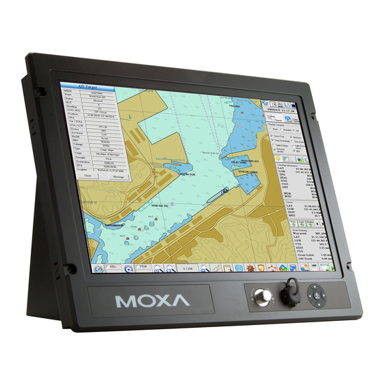
The MPC-122-K marine panel computers feature a 2.26 GHz Intel
Core 2 Duo processor with up to 4 GB of system memory, providing
high performance for system operation. The MPC-122-K
computers have 2 RS-232/422/485 serial ports for reliable serial
communications, and 2 Gigabit LAN ports for high speed Ethernet
transmission and network redundancy. Features easily accessed
from the computer's panel include full range dimming, optical
bonding, wide viewing angle, and color calibration.
2. Package Checklist
Before installing the MPC-122-K, verify that the package contains
the following items:
•
1 MPC-122-K panel computer
•
PS/2 to KB/MS Y-type cable
•
2 sets of hard disk drive cables and 1 set of SATA disk power
cables
•
Rubber water proofing cushion
•
Hard disk drive ground sticker
•
Documentation and software CD
•
Quick installation guide (printed)
•
Warranty card
Note: Please notify your sales representative if any of the above
items are missing or damaged.
3. MPC-122-K Panel Layout
B ottom View
U
Panel
P/N: 1802001220010
– 1 –
S ide and Front Views
U
Computer
Panel
C omputer
U
LED Indicators
Power Switch PS/2
(Storage, Power)
Power Input
Antenna Hole
(reserved)
L ED Indicators
U
The following table describes the LED indicators located on the
front panel of the MPC-122-K.
LED Name
LED Color
Power
Green
Off
Storage
Yellow (on)
Yellow
(blinking)
Off
LAN
Green
Yellow
Off
Computer
4. Installing the MPC-122-K
W all or Cabinet Mounting
U
There are four screw holes on each side of the panel. Place the
rubber water proofing cushion on the back of the panel, and then
use two screws per side to attach the MPC-122-K to a wall or
cabinet.
Panel
Adjustment Button
Menu Botton
USB Port with
Water-proof Cover
Gigabit Ethernet
CompactFlash
Serial Port x 2
Port x 2
Card Socket
(RS-232/422/485)
USB 2.0
Host x 6 DVI-D/VGA Output
Audio Output/Input
LED Function
Power is on and functioning normally
Power is off or power error exists
CF card is inserted and detected
Data is being read from or written to
the CF card or HDD
No activity
100 Mbps Ethernet mode
1000 Mbps (Gigabit) Ethernet mode
No activity or 10 Mbps Ethernet mode
– 2 –
Screws
5. Panel Adjustment
There are two buttons located in the right bottom corner of the
panel. Click the Menu Button to access panel adjustment items,
and then use the arrows or the Adjustment Button for each
configuration. Select Exit or push the button to close the
configuration menu.
6. Connector Description
P ower Connector
U
The MPC-122-K has an 18 to 36 VDC power input located on the
terminal block. The Power LED will light up when power is being
properly supplied. When The Ready LED lights to a solid green, the
OS is ready. When the Ready LED lights to a solid green, the OS is
ready
G rounding the MPC-122-K
U
Grounding and write routing help limit the effects of noise due to
electromagnetic interference (EMI). Run the ground connection
from the ground screw to the grounding surface prior to connecting
the power.
ATTENTION
This product is intended to be mounted to a well-grounded
mounting surface, such as a metal panel.
– 3 –
Screws
Advertisement
Table of Contents

Subscribe to Our Youtube Channel
Related Manuals for Moxa Technologies MPC-122-K


Summary of Contents for Moxa Technologies MPC-122-K
-
Page 1: Quick Installation Guide
P ower Connector • Documentation and software CD L ED Indicators The MPC-122-K has an 18 to 36 VDC power input located on the • Quick installation guide (printed) The following table describes the LED indicators located on the terminal block. The Power LED will light up when power is being •... - Page 2 Europe: +49-89-3 70 03 99-0 U SB Hosts Asia-Pacific: +886-2-8919-1230 The MPC-122-K has six USB 2.0 full speed hosts that use a type A China: +86-21-5258-9955 (toll-free: 800-820-5036) connector on the front panel of the computer. An additional USB port is located on the display. The port supports a keyboard and ...
Need help?
Do you have a question about the MPC-122-K and is the answer not in the manual?
Questions and answers