Table of Contents
Advertisement
Quick Links
Uninterruptible Power Supply (UPS)
● This manual describes the significant points to be noted to maintain the safety while using the
UPS. Therefore, ensure reading it carefully before installation and start using the UPS.
● Store this manual near the UPS so it can be referenced whenever required. This instruction
manual may not be reproduced in whole or in part without the prior permission of OMRON.
● The contents of this instruction manual may change in the future, without notice.
● A warranty is enclosed in the product package.
BL50T/BL75T/BL100T
Instruction Manual
Advertisement
Table of Contents

Related Manuals for Omron BL50T


Summary of Contents for Omron BL50T
- Page 1 ● Store this manual near the UPS so it can be referenced whenever required. This instruction manual may not be reproduced in whole or in part without the prior permission of OMRON. ● The contents of this instruction manual may change in the future, without notice.
-
Page 2: Introduction
● Be sure to observe the conditions and environment for usage described in this instruction manual. ● Please contact OMRON Electronic Equipment Customer Support Center when using the UPS for a mission critical system that particularly requires reliability. - Page 3 ● Windows is a registered trademark of Microsoft Corporation in the USA and other countries. ● Other company names and product names are the trademarks, or registered trademarks belong to their respective owners. © OMRON Corporation. 2018 All Rights Reserved BL50T/BL75T/BL100T...
-
Page 4: Procedure From Installation To Operation
Procedure from installation to operation Procedure from installation to operation Shows the procedure from installation to operation. BL50T/BL75T/BL100T... -
Page 5: Table Of Contents
Overview of the automatic shutdown software functions ......59 5-1-1 Automatic shutdown software function list ................ 60 5-1-2 The supported OS of the UPS monitoring software ............62 How to use automatic shutdown software ............. 62 5-2-1 PowerAct Pro ........................62 BL50T/BL75T/BL100T... - Page 6 RS232C card ....................75 7-4-1 Main features ........................75 If you suspect a problem..............76 If you suspect a problem................76 References ..................78 Specifications ....................78 Dimensions ....................80 Battery life ...................... 81 Input voltage sensitivity settings ..............82 BL50T/BL75T/BL100T...
-
Page 7: Safety Precautions
● Applications that may cause serious social or public damage when they fail. (E.g., applications for mission-critical computer systems, or trunk line communication systems.) ● Other applications based on the above BL50T/BL75T/BL100T... - Page 8 ● In a case of dropping the UPS, stop using the unit and immediately ask for the inspection and repair. For information about repair, contact Omron Electronics Repair Center. ● Be careful about crush injury when your fingers are in between the installation surface and the bottom surface of the UPS.
- Page 9 ● Electric shock or fire can occur due to the cable damage or overheat generation. ● Stop using the UPS if the cable has damage and immediately ask for the repair. For information about repair, contact Omron Electronics Repair Center. All the accessories contained in the product package can be used for the UPS only.
- Page 10 Ensure to check the performance before use. Do not connect devices that don't run on the commercial power supply. ● When a device error occurs, the UPS performs bypass operation, so that commercial power is supplied to the connected devices as-is. BL50T/BL75T/BL100T...
- Page 11 ● When the UPS becomes wet or drops, stop using it, pull out the AC input plug from the outlet, and ask for the inspection and repair. ● For details on repair, contact the Omron Electronic Device Repair Center . Replace the battery as soon as it reaches end of life, or discontinue the use of the UPS.
- Page 12 The battery pack should be replaced on a stable, flat place. Hold the battery pack firmly to prevent it from dropping. ● There is a danger of injury caused by a fall or burns caused by leakage (liquid electrolyte). BL50T/BL75T/BL100T...
- Page 13 Use only the specified battery for replacement. ● It may cause fire. ● Product models: Battery pack for replace: For BL50T: BLB50T For BL75T: BLB75T For BL100T: BLB100T Do not replace the battery pack in a place where combustible gas exists.
- Page 14 However, adjust the frequency of the generator to match with the commercial power supply. Prevent the short circuit between the output lines of the UPS, or the output line on the earth (grounding.) ● The UPS may fail. BL50T/BL75T/BL100T...
- Page 15 For details on recycling, either contact the Omron Electronic Device Replacement Service Center or download a replacement service form from the Omron Website, and send the filled-in form to Omron Replacement Service Center. Remove the "grounding terminal" screw on the back before conducting a withstand voltage test or insulation resistance test.
-
Page 16: Preparation
Check the accessories Check that all the accessories are contained in the package, and no damage is visually found. In case you find any defect or other problems, please contact OMRON Electronic Equipment Customer Support Center immediately. Remote ON/OFF connector... - Page 17 1 Preparation 1-2 Check the accessories BL50T/BL75T/BL100T...
-
Page 18: Related Products (Options)
1 Preparation 1-3 Related products (options) Related products (options) Product Model For BL50T: BLB50T Replacement Battery Pack For BL75T: BLB75T For BL100T: BLB100T SNMP/Web Card SC20G2 Contact Signal I/O Card SC07 (Transistor Output) Contact Signal I/O Card SC08 (Relay Output Type) -
Page 19: Name Of Each Part
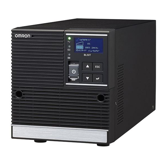
(P.27) for details on the function of each part. ■ Front ● Operation and display sections A: LCD E: ": "Up" "Down" switches B: "Power Output" LED F: "ESC" switch C: "Battery Mode" LED G: "Enter" switch D: "Battery Replace" LED H: "Power" switch/switch cover BL50T/BL75T/BL100T... - Page 20 1 Preparation 1-4 Name of Each Part ■ Back BL50T/BL75T BL100T A: USB port E: Optional slot B: Remote ON/OFF dedicated port F: AC input cable C: Cooling fan G: Power output outlet D: AC overcurrent protection switch H: Grounding terminal...
-
Page 21: I/O Circuit Block Diagram
1 Preparation 1-5 I/O circuit block diagram I/O circuit block diagram BL50T/BL75T/BL100T... -
Page 22: Installation And Connection
UPS or the serial number sticker enclosed in the product package. Make sure that there is enough room in the back of the UPS for the AC cables of the UPS and the connected devices. Use the UPS only in the correct orientation specified in the following figure. BL50T/BL75T/BL100T... - Page 23 2 Installation and connection 2-1 Install Do not install in any of the following ways. BL50T/BL75T/BL100T...
-
Page 24: How To Connect The Device To Back Up
The rated output voltage of the UPS is 100VAC. Overvoltage may damage a connected device. Disconnect all the "AC input" plugs of the power backup target devices, such as a computer and peripheral, from the power outlet (commercial power supply). BL50T/BL75T/BL100T... - Page 25 (model BUC26: UPS service (OS Standard) connection cable). Refer to "5. Connected device automatic shutdown processing" (P.59) and "6. Contact input and output function" (P.66). Note: The above is required only when using automatic shutdown software and contact signal inputs and outputs. BL50T/BL75T/BL100T...
-
Page 26: Connect The Ac Input
The UPS is shipped after being charged. However, when it is used for the first time, its backup time may have become shorter due to self-discharge. We recommend using the UPS after charging. “3-1-10 Disable screen savers” (P.36) can also be carried out before charging the battery. BL50T/BL75T/BL100T... -
Page 27: Check And Start The Operation
Orange Battery Mode LED In backup operation with Not in backup operation the battery with the battery Battery Replacement Battery replacement Battery replacement not required due to battery required deterioration or end of life of the battery or UPS BL50T/BL75T/BL100T... -
Page 28: Switch
LED, and buzzer sounds" (From P.31) References For the condition for sounding the buzzer, you can set to OFF during backup operation or Always ON. In the LCD menu, set the condition by selecting [Settings] - [Local Setting] - [Audible Alarm]. BL50T/BL75T/BL100T... -
Page 29: Status Screen On The Lcd
■ Load level The load level gauge displays the connected capacity of the connected devices as a percentage. The maximum connected capacity is shown as 100%. BL50T : 500VA/450W indicated as 100% BL75T : 750VA/680W indicated as 100% BL100T : 1000VA/900W indicated as 100%... -
Page 30: Status Screen Example
Displays the period of time for which the UPS can continue its output using power supplied from the battery in minutes. ■ Text displayed at bottom A message prompting user action is displayed. 3-1-6 Status screen example UPS running Standby screen Commercial operation mode Shutting down BL50T/BL75T/BL100T... -
Page 31: How To Interpret Icons, Led, And Buzzer Sounds
(displayed for a few Charge the battery. discharge seconds only). (Flashing) Note 1: During normal operation, the displayed message alternates between "Commercial operation mode" and "AVR mode". During battery operation, the displayed message alternates among the battery mode messages. BL50T/BL75T/BL100T... - Page 32 (Fault-E12) might be displayed. In that case, the commercial power is output as-is (charging stopped). Then, the battery temperature drops, the error display is automatically canceled, and the charging operation resumes. Note 4: Different depending on the operating condition. BL50T/BL75T/BL100T...
- Page 33 A UPS failure UPS failure ● ● ○ UPS failure change, the UPS is faulty. Contact failure occurred. your dealer or OMRON Electronic conditi Equipment Customer Support (Flashing) Center. Dependi ng on the ON or ○ ● ●...
-
Page 34: Message At Bottom
Power switch on the UPS again. stops outputting power when in backup operation. (Note 5) If the displayed content does not change, the UPS is faulty. Contact your dealer or OMRON Fault-E2 Output voltage undervoltage Electronic Equipment Customer Support Center. - Page 35 3-1Names and functions of parts in the operation and display sections Select [3. Settings] and press the switch. Select [Local Setting] and press the switch. Select [Language] and press the switch. Select [English] and press the switch. Press the [ESC] switch to check that the language has been changed. BL50T/BL75T/BL100T...
-
Page 36: Disable Screen Savers
Important notice ● The UPS is shipped after being charged. However, when it is stored for a long time, its backup time may become shorter due to self-discharge. So, we recommend charging the battery before using the UPS. BL50T/BL75T/BL100T... - Page 37 5 on the previous page. ・ If the problem cannot be solved by checking the above two points, contact Omron Electronic Equipment Customer Support Center. References In the LCD menu, set the buzzer ON/OFF condition by selecting [Settings] - [Local Setting] - [Audible Alarm] (buzzer setting).
- Page 38 The original status display condition is restored and the buzzer stops sounding (the state in the following figure arises). Icon Description "Power" switch turned ON In normal operation That’s all for the operation check. Then, the installation and connection processes are all completed. BL50T/BL75T/BL100T...
-
Page 39: Basic Operations Including Running And Stopping The Unit
■ Operation when a power outage occurs If a power outage or AC line failure occurs, the operation automatically switches to backup operation to continue the power output by using electrical power from the battery (this is called "backup operation"). BL50T/BL75T/BL100T... - Page 40 When recovery from a power outage is made, by factory default, the UPS automatically restarts and supplies power. If you do not want to activate the connected devices, either turn off their switches or disable the automatic start setting for recovery from a power outage ([Settings] - [Boot Settings] - [Auto Reboot]) BL50T/BL75T/BL100T...
- Page 41 Power switch is turned off. At the same time, the icon changes to " ". Then, the power output coming from the UPS stops. References Even if the "Power" switch is turned off, as long as AC power is supplied from the commercial power supply, the battery is charged automatically. BL50T/BL75T/BL100T...
-
Page 42: Operation By Using The Lcd Menu
■ Basic operation of the menu screen Switch Description Move the selected cursor [ ▲ ] [ ▼ ] upward/downward or increase/decrease the value. Select the menu item or determine the value. [ ESC ] Return to the menu or cancel. BL50T/BL75T/BL100T... -
Page 43: Lcd Menu Item List
Set the time until the LCD automatically LCD Auto OFF: Always ON (factory LCD Auto OFF turns off. default), Auto OFF 30 seconds, Auto OFF 3 minutes LCD Test Check that the LCD and LEDs turn on. Execute LCD test BL50T/BL75T/BL100T... -
Page 44: Operation By Using The Lcd Menu
Year, month, and day (Factory default: 2018/1/1) Set the output of the UPS to stop after a Maximum backup time: Advanced Max.backupTime☆ specified period of time. Disabled (factory default) Enabled: 10 to 999 seconds Enabled: 1 to 9999 minutes BL50T/BL75T/BL100T... - Page 45 Note 1: Refer to "9-4 Input voltage sensitivity settings". Note 2: Refer to "9-3 Battery life". Note 3: BMS stands for Battery Management System. A lead battery UPS does not require the BMS. A lithium battery UPS always are safely managed a battery condition using the BMS. BL50T/BL75T/BL100T...
-
Page 46: Maintenance And Inspection
・ With the "Power" switch turned ON (powered on), once every 4 weeks If the battery is not fully charged, the self-diagnostic test is not executed immediately. A self-diagnostic test is executed automatically when the battery is fully charged. BL50T/BL75T/BL100T... -
Page 47: How To Measure Backup Time
(Fault-E12) might be displayed. In that case, the commercial power is output as-is (charging stopped). Then, the battery temperature drops, the error display is automatically canceled, and the charging operation resumes. BL50T/BL75T/BL100T... -
Page 48: Estimated Backup Time
※ If the temperature is low, the backup times become shorter than the corresponding values in the chart (table) on the next page. ※ The backup time becomes long when the sum of the capacities of the connected devices is small. BL50T/BL75T/BL100T... - Page 49 Connection capacity (W) The above backup times are for reference only. They may change depending on the battery life and external environment (such as temperature). Backup time table (Unit of time: minutes) Load (W) BL50T 10.5 (450W) BL75T 10.5 (680W)
-
Page 50: Replacing The Battery
■ Do not replace the battery during backup operation. Otherwise, the output stops. ※ OMRON is collecting an unneeded replaced battery, with only transportation charges borne by the customer. For details, refer to the attachment "Replacement Service Leaflet". - Page 51 For the first 5 years from the After 5 years from the usage 30 degrees Celsius date of purchase start date For the first 6 years from the After 6 years from the usage 25 degrees Celsius date of purchase start date BL50T/BL75T/BL100T...
-
Page 52: Replace The Battery
), select [BMS Setting], and press the Enter switch ( Press the Down switch ( ), select [Disabled], and press the Enter switch The yellow LED starts flashing. Loosen the screws on the front panel (two locations) with a Phillips screwdriver. BL50T/BL75T/BL100T... - Page 53 4 Maintenance and inspection 4-2 Replacing the battery Detach the front panel by pulling it toward you (The screws remain on the front panel). Pull and detach the battery cable connectors (two pieces). Remove the cable on the left from the holder. BL50T/BL75T/BL100T...
- Page 54 Pull the metal cover toward you (①) and remove it while lifting it up (②) Grip the label and pull out the battery pack. ※Do not grip the connector or cable when pulling the battery pack out. ※The battery pack is heavy. Be careful not to drop it. BL50T/BL75T/BL100T...
- Page 55 ・Replacement Battery Pack Model BLB50T/BLB75T/BLB100T Insert the protrusion on the lower side of the metal cover into a groove on the main body (①), and align the protrusion on the upper side into another groove on the main body (②). BL50T/BL75T/BL100T...
- Page 56 4 Replacing the battery 4-2 Replacing the battery Fix the metal cover with a screw. Set the cable for the left side into the holder. Connect the cable connectors (two pieces). BL50T/BL75T/BL100T...
- Page 57 E11" is displayed on the LCD screen. When this occurs after battery replacement, it is not an error. Connect the battery cable connector to the connector on the UPS side, and the buzzer automatically stops sounding and "Fault-E11" is canceled. BL50T/BL75T/BL100T...
-
Page 58: Cleaning
[Settings] - [Battery Setting] - [Battery Installation] (battery replacement date) in the LCD menu. ※OMRON is collecting an unneeded replaced battery, with only transportation charges borne by the customer. For details, refer to the attached "UPS Replacement Service" pickup request. -
Page 59: Processing For The Automatic Shutdown Of The Connected Devices
● Even if a power outage occurs and power is restored during the execution of automatic shutdown processing, the output of the UPS stops once after the set time elapses. After shutdown is finished, do not turn on the computer until the UPS has finished restarting. BL50T/BL75T/BL100T... -
Page 60: Automatic Shutdown Software Function List
● ● Linked shutdown ● ● Redundant power supply support ● Remote UPS management ● ● Mail send ● Telnet connection ● ● SYSLOG support ● *This function is available only for windows. Mac and Linux are NOT available. BL50T/BL75T/BL100T... - Page 61 16. SNMP management UPS management information can be sent to SNMP Manager. 17. Telnet connection Settings such as shutdown parameters can be made via the Telnet connection. 18. SYSLOG support UPS management information can be recorded in SYSLOG form. BL50T/BL75T/BL100T...
-
Page 62: The Supported Os Of The Ups Monitoring Software
Ver.4.7, it is necessary to set OS. For details, refer to our homepage. *4 Cent OS Ver.6.x、Red Hat Linux Ver.5.x、Asianux Server 3 is not supported. How to use automatic shutdown software 5-2-1 PowerAct Pro By using the automatic shutdown software "PowerAct Pro", you can process the BL50T/BL75T/BL100T... -
Page 63: Simple Shutdown Software
For details, see the manual for the above software. You can download this software and its detailed manual from our website: http://www.omron.co.jp/ese/ups/support/download/download.html ※The user name and password are required for downloading PowerActPro (MasterAgent). For details, refer to the attached document "About the Use of Shutdown Software". BL50T/BL75T/BL100T... -
Page 64: Connection Method
● To use this product as a CE marking compliant product, use a 2-meter or shorter connection cable. Connect the UPS to your computer. Cable to be used: USB cable provided with the product To connect two or more computers to the Uninterruptible Power Supply (UPS) (PowerAct Pro only) BL50T/BL75T/BL100T... - Page 65 UPS automatically reboots and starts supplying power. If you do not want to activate the connected devices, either turn off their switches or disable the automatic start setting for recovery from a power outage ([Settings] - [Boot Settings] - [Auto Reboot]) BL50T/BL75T/BL100T...
-
Page 66: Contact Signal Functions
Battery Replacement Signal Turns ON when the deterioration of the battery and output (WB) the necessity of its replacement are detected by a test, or when the the battery life counter reaches the end of count value. BL50T/BL75T/BL100T... -
Page 67: Types Of Signal Inputs
Remote ON/OFF input (-) #4-40UNC Remote ON/OFF input (+) Backup Signal output (BU) Battery Replacement Signal output (WB) ※To fix a connector screw at the contact signal I/O port, manually tighten the screw without using an electric screwdriver. BL50T/BL75T/BL100T... -
Page 68: Remote On/Off Dedicated Port
● Remote ON/OFF Voltage between 5VDC terminals: Current when the max.10mA circuit is closed 6-1-6 Signal I/O circuit ● Signal output (BL, TR, BU, WB) ● Remote ON/OFF signal ● Backup Power Supply Stop Signal input (BS) 560Ω 2.4V BL50T/BL75T/BL100T... -
Page 69: Signal I/O Circuit Usage Example
UPS automatically reboots and starts supplying power. If you do not want to activate the connected devices, either turn off their switches or enable the automatic start setting for recovery from a power outage (No Auto Boot). BL50T/BL75T/BL100T... -
Page 70: How To Use Optional Cards
Turn the power of the main body off. Detach the optional card cover in the back by removing two screws. オプションカードカバー Insert the optional card into the main body as far as it goes so that it fits into the connector of the main body. オプションカード BL50T/BL75T/BL100T... -
Page 71: Contact Signal I/O Card
In addition, by inputting a backup stop signal from the system, it is possible to stop the UPS while the battery still remains, and become ready for the next occurrence of power outage. BL50T/BL75T/BL100T... -
Page 72: Specifications
● Backup Power Supply Stop Signal input (BS) Input voltage: High (ON) 5 to 12VDC Low (OFF) 0.7VDC or less ● Remote ON/OFF Voltage between terminals: 10VDC Current when the circuit is closed max.10mA ※For details, see the manual that comes with the contact I/O card. BL50T/BL75T/BL100T... -
Page 73: Snmp/Web Card
7 How to use optional cards 7-3 SNMP/Web card SNMP/Web card シリアル リセッ ト 通信 電源 10 100 BL50T/BL75T/BL100T... -
Page 74: Main Features
A schedule action (auto start, auto stop) can be executed via network. UPS standard MIB (RFC1628) and proprietary MIB (swc mib) installed By using a JAVA applet, the power status can be displayed in graph form and visually checked. BL50T/BL75T/BL100T... -
Page 75: Specifications
OMRON MIB Other Realtime clock installed ・ For details, see the manual that comes with the SNMP/Web card. ・ The latest firmware can be downloaded from the OMRON Website (http://www.omron.co.jp/ese/). ・ For the latest specifications, check the OMORN Website (http://www.omron.co.jp/ese/). -
Page 76: If You Suspect A Problem
Fault-E3 The mode shifts to bypass operation change, the UPS is faulty. Contact your sound (Note 3) due to a charging voltage abnormality dealer or OMRON Electronic Equipment (overvoltage) (Note 1). Customer Support Center. Continuous Undefined Fault-E4 The mode shifts to bypass operation... - Page 77 (AC input turned OFF) occurs during bypass operation, output stops. Note 2: A maximum of two types of messages may be displayed alternately on the LCD. Note 3: The output (charging, LCD display message) is different depending on the situation. BL50T/BL75T/BL100T...
-
Page 78: References
9 References 9-1 Specifications 9 References Specifications Model BL50T BL75T BL100T Operation method Line-interactive system Method Cooling method Forced air-cooling Rated input voltage AC100V 80±2 to 118±2 VAC Input voltage range Frequency 50/60Hz±5.5Hz Input Maximum current (*1) 7.5A Phase Single-phase, two-wire (grounded) - Page 79 9 References 9-1 Specifications Model BL50T BL75T BL100T Usage environment 0 to 40 degrees Celsius/25 to 85% RH (no condensation) temperature/humidity Storage temperature -15 to 50 degrees Celsius/10 to 90% RH (no condensation) Safety standards/RoHS UL1778/RoHS compatible/CE/UN38.3 compliance Emission AC power...
-
Page 80: Dimensions
9 References 9-2 Dimensions Dimensions Unit: mm/Tolerance: ±2mm ■ BL50T/BL75T ■ BL100T BL50T/BL75T/BL100T... -
Page 81: Battery Life
Battery (Ambient (Ambient (Ambient type temperature 40 temperature 30 temperature 25 degrees Celsius) degrees Celsius) degrees Celsius) Long life 5 years 8 years 10 years battery ※Basically, the ambient temperature greatly affects the life of the battery. BL50T/BL75T/BL100T... -
Page 82: Input Voltage Sensitivity Settings
More than 108VAC or less than environment 92VAC Low sensitivity 89 to 110VAC AC89V to 110V If you want to operate the AC100V±3% setting More than 110VAC or less than UPS by keeping the 89VAC frequency of fan operation BL50T/BL75T/BL100T... - Page 83 No part or whole of this manual may be reproduced without permission. The contents of this manual are subject to change without notice. NUD-D-18026A...
Need help?
Do you have a question about the BL50T and is the answer not in the manual?
Questions and answers