Table of Contents
Advertisement
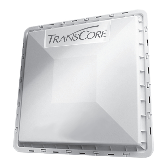
TransCore's Encompass® 4 family of fully integrated wireless radio frequency
identification (RFID) readers are designed for use in parking, security access,
electronic vehicle registration (EVR), traffic management, and low-speed
electronic toll collection applications.
This quick start guide is intended for use by authorized TransCore Encompass
series dealers, installers, and service personnel, and provides information for
site design, reader placement, testing, installation, and troubleshooting.
Encompass® 4
Quick Start Guide
16-0106-001 Rev A 4/18
Trusted Transportation Solutions
Advertisement
Table of Contents

Related Manuals for TransCore Encompass 4


Summary of Contents for TransCore Encompass 4
- Page 1 (EVR), traffic management, and low-speed electronic toll collection applications. This quick start guide is intended for use by authorized TransCore Encompass series dealers, installers, and service personnel, and provides information for site design, reader placement, testing, installation, and troubleshooting.
- Page 2 Information in this document is subject to change and does not represent a commitment on the part of TransCore, LP. © 2008-2018 TransCore, LP. All rights reserved. TRANSCORE, AMTECH, EGO, and ENCOMPASS are registered trademarks and are used under license. All other trademarks are the property of their respective owners.
-
Page 3: Table Of Contents
Before Starting Installation .......................12 Mount Reader on Round Pole or Flat Surface ..............12 Connect All Wiring ........................13 Apply Power ..........................17 Reader Set Up ..........................17 Reader Commands ................17 Troubleshooting ..................20 RF Interference or Poor Performance ..................22 TransCore Proprietary... - Page 4 List of Figures Figure 1 Recommended Reader Grounding ................9 Figure 2 Frequency Separation for Four Lanes ..............10 Figure 3 RS–232 Wiring Diagram .................... 15 Figure 4 RS–422 Wiring Diagram .................... 16 Figure 5 Sources of RF Interference ..................23 TransCore Proprietary...
-
Page 5: Site Licensing
FCC site license. Designing the Site Plan Design the site plan before ordering equipment and installing the Encompass 4 Reader. If the site configuration differs significantly from the recommendations in this guide, contact TransCore Sales Support. Determine the Reader and Tag Combination The Encompass 4 Reader is capable of reading the following protocols and formats: •... -
Page 6: Reader Placement
Tag Placement on Vehicle Most TransCore RFID tags should be mounted in the center of the windshield to the right of the rear- view mirror post. Refer to the installation instructions for your specific tag for more information on tag placement. -
Page 7: Pre-Installation Testing
3. Connect the leads from the audible tester to the red and white pair of wires from the power/communications cable. 4. For RS–232 units, refer to Table 3 for wiring instructions. For RS–422 units, refer to Table 4. 5. Connect the communications cable to the appropriate terminal on the host computer. TransCore Proprietary... -
Page 8: Table 3 Rs-232 Interface
Pin 3 Pin 2 Yellow/Black Yellow Pin 5 Pin 7 Table 4 RS–422 Interface Colored Wire Pair Use This Color Connect to Host Signal Yellow Receive (+) Yellow/Red Receive (-) Black Transmit (+) Red/Black Transmit (-) Yellow/Black Yellow Signal Ground TransCore Proprietary... -
Page 9: Correct Reader Grounding
2. Once the reader has been powered up, a sign-on message will appear. If startup is successful, the sign-on message appears as follows: Model E4 Series [software version] SNYYYYYY [Copyright notice] Where YYYYYY is the serial number of the Encompass 4 Reader unit being used. TransCore Proprietary... -
Page 10: Frequency Plan
Table 5 Reader Frequencies Staggered for 14 Lanes Reader Reader Lane #642 #647 Lane #642 #647 Frequency Frequency 912.50 915.00 917.50 913.50 916.00 918.50 914.50 917.00 913.00 915.50 918.00 914.00 916.50 919.00 TransCore Proprietary... -
Page 11: Configure For Wiegand Operation
#6401 #Done Turns RF ON Returns reader to data mode and saves #Done settings to NVM Table 8 Wiegand Interface Connect to Data Wire of Colored Wire Pair Use This Color Wiegand Controller Blue Data0 Blue/Red Data1 Yellow/Black Black Ground TransCore Proprietary... -
Page 12: Read Test Tags
CAUTION: For reliable reader operation, ensure that the reader is connected to Earth Ground. Connect the cable shield of the communications cable to Earth Ground. TransCore strongly recommends following the National Electric Code for lightning protection for the locale TransCore Proprietary... -
Page 13: Connect All Wiring
Tag lock output, active- White Lock Testing/maintenance closed White/Red Lock_RTN Tag lock return Testing/maintenance Loop and presence Green Sense Input0 Sense Input0 (loop) detection Green/Red Sense Input0 return; Loop and presence Sense Input0_RTN not isolated from signal detection ground TransCore Proprietary... - Page 14 Green/Black Sense Output1 Green Sense Output1_NO Switched sense output normally open terminal Sense Output1, Black Sense Output1_ COM Switched sense output common terminal White/ Black Sense Output1 White Sense Output1_NC normally closed Switched sense output terminal TransCore Proprietary...
-
Page 15: Figure 3 Rs-232 Wiring Diagram
Wiring Diagram for an Encompass® 4 (RS–232) Unit Terminal Block Encompass 4 Connector Twisted Pairs RxD, Pin2 for DB9 or Pin3 for DB25 Black (Black/Red Pair) TxD RS–232 TxD, Pin3 for DB9 or Pin2 for DB25 Red (Black/Red Pair) RxD SIG GND, Pin5 for DB9 or Pin7 for DB25 Yellow (Yellow/Black Pair) Signal Ground Black (Yellow/Black Pair) Signal Ground... -
Page 16: Figure 4 Rs-422 Wiring Diagram
Wiring Diagram for an Encompass® 4 (RS–422) Unit 12V AC Terminal Block Encompass 4 Connector RS–232 PWR RTN Twisted Pairs LDM422 Receive (-) Red (Yellow/Red Pair) Tx (-) Pin3 for DB9 or Pin2 Converter for DB25 RD B Receive (+) Yellow (Yellow/Red Pair) Tx (+) Pin 2 for DB9 or Pin3 for DB25... -
Page 17: Apply Power
Disable Wiegand mode (Default) #Done #451 #Done Enable Wiegand mode, See #532 #454 Disable Multitag Sort (Default) #Done #455 #Done Enable multi-tag sort Set Wiegand retransmit interval in seconds #46NN #Done NN = 01–FF Hex (01 Default) See#533 TransCore Proprietary... - Page 18 Gxx = eATA SeGo/eGo range control, 00 to 1F (Default =1F = max range) , see #645NN Axx = RF power attenuation, 00 to 0A (Default = 00 = Max Power), see #644NN Ixx (IAG Attenuation) = 00-0F (04 Default) 00=Max Power, see #646NN TransCore Proprietary...
- Page 19 (00 to 1F Hex) 1F = max range (Default) #644NN Set RF attenuation in 1.0 dB increments; 0 to 20 (00 – 14) #Done dB, 00=max power for max range #645NN Set operating range for eGo and SeGo #Done protocols TransCore Proprietary...
-
Page 20: Troubleshooting
For the external antenna-series Encompass 4 Readers, long RF cable runs between the reader and the antenna may cause signal degradation or loss. This scenario may be site-specific, but TransCore recommends limiting antenna cable runs to less than 3dB of cable loss. - Page 21 Different commands were likely used to support the other site. Restore the factory defaults by issuing command #66F. The factory defaults will be restored except for RF operating frequency, which will be retained. TransCore Proprietary...
-
Page 22: Rf Interference Or Poor Performance
Interference from RF and electrical sources can interfere with the optimal operation of the system. Any RF interference at the site should be shielded, removed, or positioned farther from the Encompass 4 Reader if possible. Figure 5 Sources of RF Interference TransCore Proprietary... - Page 24 Trusted Transportation Solutions © 2008-2018 TransCore LP. All rights reserved. TRANSCORE is a registered trademark, and is used under license. All other trademarks listed are the property of their respective owners. Contents subject to change. Printed in the U.S.A.
Need help?
Do you have a question about the Encompass 4 and is the answer not in the manual?
Questions and answers