Table of Contents
Advertisement
Quick Links
Contour Crimp
CONTROLLED CYCLE
CRIMPING TOOL
Crimps most Panduit #22-#10 AWG
insulated terminals & splices; and
specific insulated disconnects.
Reduced crimp effort advantage
for #22-#14 AWG terminations.
Provides UL Listed and CSA Certified terminations
with applicable Panduit terminals.
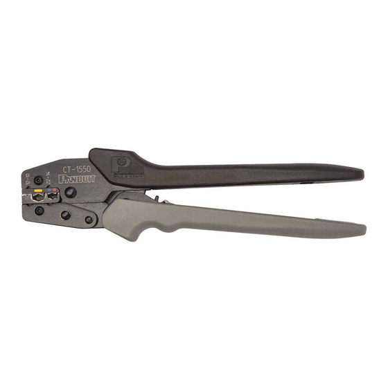
Part No. CT-1550
OPERATION INSTRUCTIONS
INSULATED TERMINAL CRIMPING
INSTRUCTIONS
1. With the handles in the closed position, (See
Figure 1), rotate the locator until the narrow slot
is centered between the crimp pockets (See
Figure 2). The locator will detent and "lock" in
this position. Squeeze the handles to open the
tool.
With the back of the terminal tongue
turned toward the color dots, insert the terminal
in the proper crimp pocket (See Figure 1) so
that the tongue slides into the locator slot (See
Figure 3).
Refer to product packaging for
selection of proper crimp pocket.
2. Hold the terminal against the locator and close
the handles until the barrel is held snugly in
place—do not deform the barrel.
3. Insert the stripped wire into the terminal until
the wire stops in the recessed slot in the
locator. Refer to product packaging for wire
strip length.
4. Crimp the terminal by closing the handles until
the controlled cycle mechanism releases.
Upon release, the handles will open automati-
cally and the crimped terminal can be removed.
NOTE: Visual inspection dots (formed by the
crimp dies) on the insulation sleeve verify
proper crimp cycle.
• Two (2) dots for red and blue crimp
pocket
• Three (3) dots for yellow crimp pocket.
INSULATED SPLICE AND FULLY
INSULATED DISCONNECT CRIMPING
INSTRUCTIONS
1. With the handles in the open position, swing the locator out of the way (See Figure 4). The locator will detent and "lock"
in this position. For splices, insert the splice in the proper crimp pocket (See FIgure 1) so that the crimp is located on
the barrel of the splice (See Figure 5). For fully insulated disconnects, insert the disconnect in the proper crimp pocket
(See Figure 1) so that the crimp is located on the barrel of the disconnect (See Figure 6). Refer to product packaging
for selection of proper crimp pocket.
2. Close the handles until the barrel is held snugly in position—do not deform the barrel.
3. Insert the stripped wire into the barrel until the wire stops. Refer to product packaging for wire strip length. Crimp by
closing the handles until the controlled cycle mechanism releases. Upon release, the handles will open automatically
and the crimped splice or disconnect can be removed. After crimping, inspect that the crimp is centered on the
disconnect barrel in order to achieve optimal pullout performance.
4. For splices, remove the splice and repeat operation for crimping the other end of the splice.
Email:
techsupport@panduit.com
EU Website: www.panduit.com/emea
EU Email: emeatoolservicecenter@panduit.com
CT-1550
© Panduit Corp. 2017
Die Closure Alignment
(not a crimp pocket)
Figure 1
12 - 10
22 - 14
CAUTION: Verify power is "OFF"
before working on wiring with this
tool.
The cushioned grips are for
the user 's comfort, and are not
intended to insulate against shock
while working on live electrical
circuits.
www.panduit.com
Page: 1 of 2
OPERATION INSTRUCTIONS
Figure 2
Locator
12 - 10
22 - 14
CRIMP POCKETS FOR
Pan-Term INSULATED
terminals, disconnects,
splices and wire joints.
Refer to product packaging
for wire range and proper
crimp pocket. Crimp pockets
are color coded to match
color of terminal insulator,
and identified with applicable
wire range.
Controlled cycle mechanism
prevents tool from opening
before crimp cycle is completed.
Manual release lever, push
forward in the event that
controlled cycle mechanism
must be released.
Cushioned Handle Grips
Panduit Europe • EMEA Service Center
Tel: 31 (0) 546 580 452 • Fax: 31 (0) 546 580 441
PA22151A04
Rev.: 06 1-2017
Figure 3
Figure 4
Figure 5
Figure 6
Figure 7
Technical Support:
Tel: 1-800-777-3300
Advertisement
Table of Contents

Related Manuals for Panduit CT-1550


Summary of Contents for Panduit CT-1550
- Page 1 4. For splices, remove the splice and repeat operation for crimping the other end of the splice. Email: Technical Support: techsupport@panduit.com Tel: 1-800-777-3300 EU Website: www.panduit.com/emea Panduit Europe • EMEA Service Center www.panduit.com EU Email: emeatoolservicecenter@panduit.com Tel: 31 (0) 546 580 452 • Fax: 31 (0) 546 580 441 Page: 1 of 2...
-
Page 2: Troubleshooting
Panduit EMEA Service Center for technical assistance. 5. If both gage conditions are met, the tool is dimensionally correct. If either condition fails, contact Panduit Customer Service, or Panduit EMEA Service Center for technical assistance. Page: 2 of 2...
Need help?
Do you have a question about the CT-1550 and is the answer not in the manual?
Questions and answers