Table of Contents
Advertisement
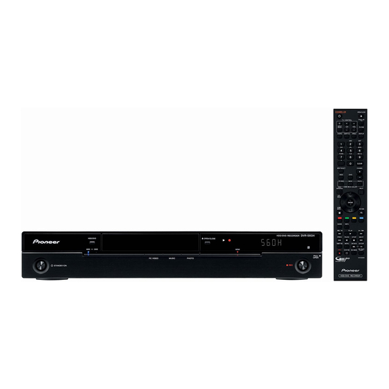
HDD/DVD RECORDER
DVR-LX61
DVR-560H-S
DVR-560H-K
THIS MANUAL IS APPLICABLE TO THE FOLLOWING MODEL(S) AND TYPE(S).
Model
Type
DVR-LX61
WYXK5
DVR-LX61
WYXV5
DVR-560H-S
WYXK5
DVR-560H-S
WYXV5
DVR-560H-K
WYXK5
DVR-560H-K
WYXV5
For details, refer to "Important Check Points for good servicing".
PIONEER CORPORATION
PIONEER ELECTRONICS (USA) INC. P.O. Box 1760, Long Beach, CA 90801-1760, U.S.A.
PIONEER EUROPE NV Haven 1087, Keetberglaan 1, 9120 Melsele, Belgium
PIONEER ELECTRONICS ASIACENTRE PTE. LTD. 253 Alexandra Road, #04-01, Singapore 159936
PIONEER CORPORATION
Power Requirement
AC 220 V to 240 V
AC 220 V to 240 V
AC 220 V to 240 V
AC 220 V to 240 V
AC 220 V to 240 V
AC 220 V to 240 V
4-1, Meguro 1-chome, Meguro-ku, Tokyo 153-8654, Japan
2008
DVR-LX61
Region No.
Please Confirm 3rd & 4th
2
&&UK######$$
2
&&DL######$$
2
&&UK######$$
2
&&DL######$$
2
&&UK######$$
2
&&DL######$$
T-IZA-001 APR.
ORDER NO.
RRV3734
Serial No.
alphabetical letters.
2008 Printed in Japan
Advertisement
Table of Contents


Need help?
Do you have a question about the DVR-560H-S and is the answer not in the manual?
Questions and answers