Table of Contents
Advertisement
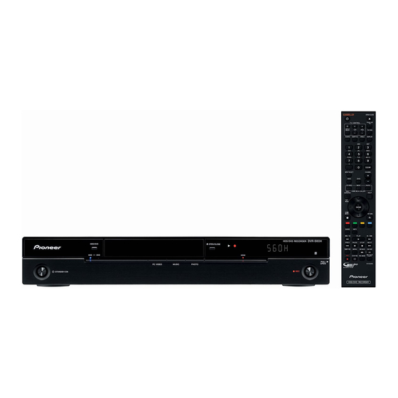
HDD/DVD RECORDER
DVR-LX61
DVR-560H-S
DVR-560H-K
THIS MANUAL IS APPLICABLE TO THE FOLLOWING MODEL(S) AND TYPE(S).
Model
Type
DVR-LX61
WYXK5
DVR-LX61
WYXV5
DVR-560H-S
WYXK5
DVR-560H-S
WYXV5
DVR-560H-K
WYXK5
DVR-560H-K
WYXV5
For details, refer to "Important Check Points for good servicing".
PIONEER CORPORATION
PIONEER ELECTRONICS (USA) INC. P.O. Box 1760, Long Beach, CA 90801-1760, U.S.A.
PIONEER EUROPE NV Haven 1087, Keetberglaan 1, 9120 Melsele, Belgium
PIONEER ELECTRONICS ASIACENTRE PTE. LTD. 253 Alexandra Road, #04-01, Singapore 159936
PIONEER CORPORATION
Power Requirement
AC 220 V to 240 V
AC 220 V to 240 V
AC 220 V to 240 V
AC 220 V to 240 V
AC 220 V to 240 V
AC 220 V to 240 V
4-1, Meguro 1-chome, Meguro-ku, Tokyo 153-8654, Japan
2008
DVR-LX61
Region No.
Please Confirm 3rd & 4th
2
&&UK######$$
2
&&DL######$$
2
&&UK######$$
2
&&DL######$$
2
&&UK######$$
2
&&DL######$$
T-IZA-001 APR.
ORDER NO.
RRV3734
Serial No.
alphabetical letters.
2008 Printed in Japan
Advertisement
Table of Contents

Related Manuals for Pioneer DVR-560H-K


Summarization of Contents
SAFETY INFORMATION
Laser Pickup specifications and Laser characteristics
Specifications for CD and DVD laser pickup.
Additional Laser Caution
Cautions regarding laser diode operation and exposure.
[Important Check Points for Good Servicing]
1. Product safety
Conformance to product regulations and safe servicing environment.
2. Adjustments
Optimum adjustments and confirmation of characteristics.
3. Lubricants, Glues, and Replacement parts
Use of specified lubricants, glues, and replacement parts.
1. SERVICE PRECAUTIONS
1.1 NOTES ON SOLDERING
Precautions for using lead-free solder and soldering irons.
1.2 NOTES ON HANDLING THE HDD
Cautions on handling the HDD due to sensitivity to shock and static.
1.3 NOTES ON REPLACEMENT OF THE SDRAM
Notes on identifying SDRAM manufacturers and replacement procedures.
2. SPECIFICATIONS
2.1 ACCESSORIES
List of included accessories such as remote control, cables, and batteries.
2.2 SPECIFICATIONS
Detailed technical specifications for DVR-LX61.
Input/Output
AV Connectors (21-pin connector assignment)
Pin assignments for AV connectors.
Supported accessories
List of supported accessories.
[2] For DVR-560H-S,-K
Model Specific Specifications
General, readable discs, and format specifications for DVR-560H models.
Recording Specifications
Video, audio, and HDD recording time specifications.
Gracenote
Gracenote Database Information
Information about Gracenote database and its update.
2.3 DISC/CONTENT FORMAT
DISC/CONTENT FORMAT
Compatibility of different disc types and content formats.
Using DVD-R/DVD-R DL/DVD-R DL discs
Using DVD-R/DVD-R DL/DVD-R DL discs
Details on using DVD-R DL discs and their compatibility.
Other disc specifications
Other disc specifications
Specifications for other disc types like Audio CD, CD-R/RW, and compressed audio.
WMA (Windows Media™ Audio) content
WMA (Windows Media™ Audio) content
Information on WMA content playback and format.
DivX video compatibility
DivX video compatibility
Compatibility and features of DivX video playback.
JPEG file compatibility
JPEG file compatibility
Compatibility of JPEG files, including format and resolution.
PC-created disc compatibility
PC-created disc compatibility
Compatibility of discs created on a PC, especially with software publisher.
Dolby Digital
Dolby Digital
Information about Dolby Digital licensing.
About the internal hard disk drive
About the internal hard disk drive
Details about the HDD, its potential issues, and protective measures.
Optimizing HDD performance
Optimizing HDD performance
How to record and edit HDD performance for optimal results.
2.4 PANEL FACILITIES
[1] Rear Panel
Description of connectors and terminals on the rear panel.
[2] Front Panel (for DVR-LX61)
Front Panel Indicators and Controls
Description of front panel indicators, buttons, and ports.
[3] Front Panel (for DVR-560H-S,-K)
Front Panel Components
Description of front panel indicators, buttons, and ports for DVR-560H models.
[4] Display
Display Indicators
Explanation of the meaning of various display indicators and symbols.
[5] Remote Control Unit
Basic Operation Controls
Controls for power, input, audio, and basic navigation.
Playback and Recording Controls
Buttons for playback, recording, and one-touch copy functions.
Menu and Channel Navigation
Controls for home menu, GUIDE Plus+™, and channel selection.
3. BASIC ITEMS FOR SERVICE
3.1 CHECK POINTS AFTER SERVICING
Procedures to check after servicing and before shipping.
[1] Cleaning
Cleaning procedures for pickup lenses and fans.
[2] Necessary Procedure List When Replacing Assys
Necessary Procedures List When Replacing Assys
List of necessary procedures and product state after replacing major assemblies.
3.2 QUICK REFERENCE
Description of work
Quick reference for service procedures and associated jigs.
3.3 PCB LOCATIONS
LIST OF ASSEMBLIES
Lists PCB assemblies, their descriptions, and part numbers.
3.4 JIGS LIST
[1] Jigs List
List of jigs used for adjustment and diagnosis.
4. BLOCK DIAGRAM
4.1 OVERALL WIRING DIAGRAM
Overall wiring diagram illustrating component interconnections.
4.2 OVERALL BLOCK DIAGRAM
A SERVICE TUSB ASSY
Block diagram of the TUSB Assy, showing tuner and decoder connections.
B SERVICE FRJB ASSY
Block diagram of the FRJB Assy, showing tuner and input connections.
SERVICE MAIN ASSY
D SERVICE MAIN ASSY
Block diagram of the main Assy, showing ICs and connections.
ETAB ASSY
E ETAB ASSY
Block diagram of the ETAB Assy, showing connections to flash memory and LAN.
4.3 POWER BLOCK DIAGRAM
G POWER SUPPLY ASSY
Power block diagram, showing power distribution to various assemblies.
5. DIAGNOSIS
5.1 SETUP SEQUENCE
Flowchart describing the system startup sequence for diagnosis.
5.2 DIAGNOSIS OF THE MAIN ASSY
Diagnosis of the MAIN ASSY
Troubleshooting flowchart for main assembly issues based on symptoms.
[1] Diagnosis of the HDMI Block
Diagnosis of the HDMI Block
Flowchart for diagnosing HDMI video output issues.
2. In a case when only the HDMI audio is not outputted
Diagnosis of HDMI audio output
Troubleshooting flowchart for HDMI audio output problems.
6. SERVICE MODE
Overview and Purposes
Explains the purpose and displays of the service mode.
Service Mode Map
Lists available service modes, their procedures, and when to use them.
6.1 VERSION INFORMATION, ETC. (FIRST SCREEN)
(1) First screen
Displays version, HDD info, and other system details.
[1] Simple Diagnosis of the RF Level (Subscreen 1)
Simple Diagnosis of the RF Level (Subscreen 1)
Checks RF signal and AGC voltage for tuner input.
[2] Simple Error Rate Measurement (Subscreen 2)
Simple Error Rate Measurement (Subscreen 2)
Measures error rates for VR mode and DVD playback.
[3] HDD Information (Subscreen 3)
HDD Information (Subscreen 3)
Displays HDD information, including life time and usage data.
[4] OSD Filter Setting (Subscreen 4)
OSD Filter Setting (Subscreen 4)
Adjusts OSD filter response to reduce character flicker.
6.2 ATA/ATAPI DEBUG SCREEN (SECOND SCREEN)
[1] Writer Maintenance Information of ATA/ATAPI DEBUG OSD (Subscreen 3)
Displays writer maintenance information and LD emission time.
[2] LD Degration Judgment of ATA/ATAPI DEBUG OSD (Subscreen 4)
LD Degradation Judgment (Subscreen 4)
Judges LD degradation based on CD and DVD read values.
6.3 VR-RECORDING-RELATED ERROR LOGS (FOURTH SCREEN)
(1) VR-Recording-Related Error Logs (Subscreen 1)
Displays VR recording error logs categorized by source.
[1] Description of VR-Recording-Related Errors
Error Related to MPEG Encoder
Lists error messages and causes related to the MPEG encoder.
Error Related to Drive System
Lists error messages and causes related to the drive system.
Error Related to Dubbing
Lists error messages and causes related to dubbing operations.
Error Related to Dubbing (Continued)
Error Related to Dubbing (Continued)
Lists more error messages and causes related to dubbing.
Other Errors
Other Errors
Lists various error messages not categorized elsewhere.
Other Errors (continued)
Other Errors (continued)
Continues the list of miscellaneous error messages.
Error Related to HDD
Error Related to HDD
Lists error messages and causes related to the hard disk drive.
6.4 VR-PLAYBACK-RELATED ERROR LOGS (FIFTH SCREEN)
(2) VR-Playback Error Logs (Subscreen 2)
Displays VR playback error logs and potential causes.
[1] Description of VR-Playback-Related Errors
Error Message Details of error
Details of various VR playback error messages and their descriptions.
6.5 DV SERVICE MODE
[1] DV Debug
Checks communication between DV device and the unit.
6.6 EPG SERVICE MODE
Summary screen
Displays EPG data acquisition status and error logs.
2. Detail screen
Detail screen
Displays detailed EPG reception error logs and related information.
6.7 HDMI SERVICE MODE
HDMI Main Information Screen
Displays connection status, resolution, audio, and TMDS signal for HDMI devices.
HDMI Signal Output Details
Information on output color, TMDS status, HDCP, and audio sampling frequency.
6.8 AGING MODE
Aging for the DVD-RW/+RW/-RAM
Aging mode operations for DVD-RW/+RW/-RAM discs.
Aging for the DVD-R/+R
Aging mode operations for DVD-R/+R discs.
Aging for the HDD
Aging mode operations for the HDD, including data erasure.
6.9 USB CHECK MODE
How to enter this mode
Steps to enter the USB check mode for port operation testing.
Procedures
Steps to check USB port operation and indicators.
Troubleshooting
Flowchart to diagnose USB cable and connection issues.
6.10 HDD CHECK MODE
[1] How to Diagnose Failure of the Hard Disc Drive (HDD)
Purpose and symptoms for diagnosing HDD failures.
[2] Flow of HDD Diagnosis
Flowchart outlining the HDD diagnosis steps.
(2) Overview of the diagnosis items
HDD Information
Displays HDD model, power-on time, and diagnostic results.
SELF TEST
Performs a simplified diagnosis for the HDD.
EXTENDED SELF TEST
Reads all sectors of the HDD for diagnosis.
HDD Read / Write Check
Tests HDD sectors by writing and reading data.
[3] How to Start or Terminate the Diagnostic Program
How to Start or Terminate the Diagnostic Program
Instructions for starting and stopping the HDD diagnostic program.
[4] Diagnosis Procedures
Diagnosis Procedures
Steps to navigate the diagnostic menu and check HDD information.
Execute Self-Test
Execute Self-Test
Instructions for performing and interpreting the HDD Self-Test results.
Execute the Ext (Extended) Self-Test
Execute the Ext (Extended) Self-Test
Instructions for performing and interpreting the Extended Self-Test results.
Execute the HDD R/W Check
Execute the HDD R/W Check
Instructions for performing and interpreting the HDD Read/Write Check.
6.11 DIAGNOSTIC PROCEDURES WHEN AAC DECODING HAS FAILED
[1] AAC information
Displays AAC error information and possible causes for failure.
Description of error codes
Description of error codes
Explains error codes related to file format and decoding issues.
Possible causes for errors and how to diagnose
Possible causes for an FMT error
Diagnosing FMT errors by checking MP4 file box size.
How to check the box size
Procedure for checking MP4 file box size using Binary Editor.
Possible cause 2: Failure in data reading during file analysis
Diagnosing data reading failures by checking the ATA error log.
How to check the ATA error log
Steps to display and check the ATA error log.
Possible causes for a DEC error
Possible causes for a DEC error
Diagnosing DEC errors due to stream errors or data reading failures.
Possible causes for a QNT error
Possible causes for a QNT error
Diagnosing QNT errors related to quantization bits.
Possible causes for a BPS error
Possible causes for a BPS error
Diagnosing BPS errors related to average bit rate.
Possible causes for an FS error
Possible causes for an FS error
Diagnosing FS errors related to sampling frequency.
Possible causes for a BOX error
Possible causes for a BOX error
Diagnosing BOX errors related to file structure and audio streams.
Possible causes for a PRF error
Possible causes for a PRF error
Diagnosing PRF errors related to AAC audio stream properties.
Possible causes for an MEM error
Possible causes for an MEM error
Diagnosing MEM errors related to system memory fragmentation.
DIAGNOSTIC PROCEDURES WHEN CONNECTING THE LAN
[1] Specifications of the Ether Debug Screen
Displays Ethernet connection information for diagnosis.
[2] Simple diagnostic procedures
Checks Ethernet connection status and IP address settings.
7. DISASSEMBLY
1 Bonnet
Procedure for removing the unit's bonnet.
2 Tray Panel
Procedures for opening and removing the tray panel.
3 Front Panel Section
Front Panel Section Procedures
Steps for removing the front panel.
4 HDD
HDD Removal
Procedures for removing the HDD and its stay.
5 SERVICE LOADER MAIN
SERVICE LOADER MAIN Procedures
Steps for removing the SERVICE LOADER MAIN assembly.
6 Diagnosis
Diagnosis Procedures
Steps for reassembling and connecting cables for diagnosis.
Access to the SERVICE MAIN Assy, Cleaning the Pickup Lens
Cord Holder
Procedure for removing the cord holder.
Low Case U11, Upper Case
Procedures for removing the low case and upper case.
8. EACH SETTING AND ADJUSTMENT
8.1 MODEL SETTING
Setting the correct model name, destination, and region number.
8.2 LD POWER ADJUSTMENT
Explanation on each adjustment mode
Explains Drive Adjustment, PU Data Setting, and Power Adjustment modes.
How to enter Drive Adjustment Mode
Steps to enter the Drive Adjustment Mode using the remote control.
Operation procedure
Operation procedure
Detailed steps for performing LD power adjustment and data setting.
Power Adjustment Mode
Power Adjustment Mode
Steps for executing and checking LD power adjustment and disc judgment.
[Error information]
Error information
Explains error indications during power adjustment and contents to check.
8.3 CPRM ID NUMBER AND DATA SETTING
The Input is Necessary When
Conditions requiring CPRM ID input, such as 'CPRM ERR' or assembly replacement.
Important
Notes on ID label and data input procedures.
[1] Input Flow of the ID No. and ID Data When Exchanging HDD or MAIN Assy
Input Flow of ID No. and ID Data
Flowchart for inputting ID number and data after HDD or MAIN Assy exchange.
[2] How to Input the ID Number and ID Data
How to Input the ID Number and ID Data
Step-by-step guide for inputting ID number and data disc.
[How to Confirm the ID Number]
How to Confirm the ID Number
Procedure to confirm the set ID number.
[How to Clear the ID Number]
How to Clear the ID Number
Procedure to clear the set ID number.
8.4 FIRMWARE UPDATE METHOD
[Purposes]
Reasons for firmware updating, such as assembly replacement or symptom amelioration.
[1] Disc Update
Procedure for updating firmware using an update disc.
[Tips]
Firmware Update Tips
Notes on updating firmware, especially after incorrect termination.
[2] Serial Update
Serial Update Procedure
Procedure for updating firmware via serial connection when disc update fails.
8.5 GRACENOTE DATABASE UPDATE METHOD
[Purposes]
Reasons for updating Gracenote DB, such as HDD replacement or missing CD titles.
[1] Disc Update
Procedure for updating Gracenote database using an update disc.
[Diagnosis Flowchart]
Gracenote Database Diagnosis Flowchart
Flowchart for diagnosing Gracenote DB errors and system operation.
8.6 VIDEO ADJUSTMENT FOR SPECIFIC AREA
[1] Specific-Channel Setting Mode
Mode for setting video parameters for specific channels to correct flicker.
[2] General Setting Mode
General Setting Mode
General video settings for tuner or line inputs.
Table 1: key operations in specific-area setting mode (1/2)
Key Operations in Specific-Area Setting Mode
Details key operations for specific-area and general setting modes.
Table 1: key operations in specific-area setting mode (2/2)
Key Operations in Specific-Area Setting Mode
Continues key operations for specific-area and general setting modes.
9. EXPLODED VIEWS AND PARTS LIST
9.1 PACKING SECTION
Exploded view and parts list for the packing section.
(1) PACKING SECTION PARTS LIST
PACKING SECTION PARTS LIST
Detailed list of parts for the packing section.
(2) CONTRAST TABLE
CONTRAST TABLE
Table comparing parts across different models.
9.2 EXTERIOR SECTION
EXTERIOR SECTION
Exploded view of the exterior components.
(1) EXTERIOR SECTION PARTS LIST
EXTERIOR SECTION PARTS LIST
Detailed list of exterior parts with part numbers.
9.3 FRONT PANEL SECTION (DVR-LX61)
FRONT PANEL SECTION (DVR-LX61) PARTS LIST
Detailed parts list for the DVR-LX61 front panel.
9.4 FRONT PANEL SECTION (DVR-560H-S,-K)
FRONT PANEL SECTION (DVR-560H) PARTS LIST
Detailed parts list for the DVR-560H front panel.
9.5 SERVICE LOADER MAIN SECTION
SERVICE LOADER MAIN SECTION PARTS LIST
Detailed parts list for the service loader main assembly.
10. SCHEMATIC DIAGRAM
10.1 SERVICE TUSB ASSY (1/4)
Schematic diagram for the TUSB Assy.
10.2 SERVICE TUSB ASSY (2/4)
Schematic diagram for the TUSB Assy.
10.3 SERVICE TUSB ASSY (3/4)
Schematic diagram for the TUSB Assy.
10.4 SERVICE TUSB ASSY (4/4)
Schematic diagram for the TUSB Assy.
10.5 SERVICE FLKY ASSY
SERVICE FLKY ASSY
Schematic diagram for the FLKY Assy.
SERVICE FRJB ASSY
SERVICE FRJB ASSY
Schematic diagram for the FRJB Assy.
10.6 SERVICE MAIN ASSY (1/5)
SERVICE MAIN ASSY (1/5)
Schematic diagram for the MAIN Assy.
10.7 SERVICE MAIN ASSY (2/5)
SERVICE MAIN ASSY (2/5)
Schematic diagram for the MAIN Assy.
10.8 SERVICE MAIN ASSY (3/5)
SERVICE MAIN ASSY (3/5)
Schematic diagram for the MAIN Assy.
10.9 SERVICE MAIN ASSY (4/5)
SERVICE MAIN ASSY (4/5)
Schematic diagram for the MAIN Assy.
10.10 SERVICE MAIN ASSY (5/5)
SERVICE MAIN ASSY (5/5)
Schematic diagram for the MAIN Assy.
10.11 ETAB ASSY (DVR-LX61 ONLY)
ETAB ASSY (DVR-LX61 ONLY)
Schematic diagram for the ETAB Assy.
10.12 SERVICE DVUB ASSY
SERVICE DVUB ASSY
Schematic diagram for the DVUB Assy.
10.13 POWER SUPPLY ASSY
POWER SUPPLY ASSY
Schematic diagram for the Power Supply Assy.
10.14 WAVEFORMS
SERVICE TUSB ASSY
Oscilloscope waveforms for various test points on the TUSB Assy.
11. PCB CONNECTION DIAGRAM
11.1 SERVICE FRJB ASSY
PCB connection diagram for the FRJB Assy.
11.2 SERVICE TUSB ASSY
PCB connection diagram for the TUSB Assy.
11.3 SERVICE FLKY ASSY
PCB connection diagram for the FLKY Assy.
11.4 SERVICE MAIN ASSY
PCB connection diagram for the MAIN Assy.
11.5 ETAB ASSY (DVR-LX61 ONLY)
PCB connection diagram for the ETAB Assy.
11.6 SERVICE DVUB ASSY
PCB connection diagram for the DVUB Assy.
11.7 POWER SUPPLY ASSY
PCB connection diagram for the Power Supply Assy.
12. PCB PARTS LIST
LIST OF ASSEMBLIES
List of PCB assemblies with part numbers for different models.
MISCELLANEOUS
List of miscellaneous components with part numbers.
Need help?
Do you have a question about the DVR-560H-K and is the answer not in the manual?
Questions and answers