Moxa Technologies NPort DE-211 Quick Installation Manual
Hide thumbs
Also See for NPort DE-211:
- Hardware installation manual (35 pages) ,
- Quick installation manual (8 pages) ,
- Tech note (5 pages)
Advertisement
Quick Links
NPort DE-211
Quick Installation Guide
Seventh Edition, May 2011
Overview
Welcome to Moxa's NPort Express DE-211, a compact palm-sized
data communication device that allows you to control
RS-232/422/485 serial devices over a TCP/IP based Ethernet
network.
Package Checklist
Before installing the NPort Express DE-211, verify that the
package contains the following items:
•
1 NPort Express DE-211
•
NPort DE-211 quick installation guide
•
Documentation and software CD
•
Warranty card
Optional Accessories
•
NP21101: RS-232 cable: DB25 (M) to DB9 (F), 30 cm
NP21102: RS-232 cable: DB25 (M) to DB9 (M), 30 cm
•
•
NP21103: DB25 Terminal Block Kit for RS-422/485
•
DK-35A: DIN-Rail Mounting Kit (35 mm)
Notify your sales representative if any of the above items are
missing or damaged.
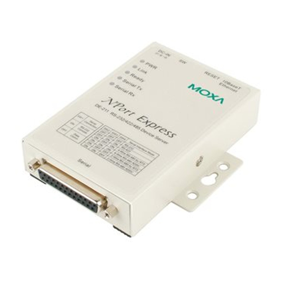
Hardware Introduction
The NPort DE-211 device server has one female DB25 serial port.
The four DIP switches located on the rear panel are used to select
RS-232 COM mode, and one of four data modes: RS-232, RS-422,
4-wire RS-485, and 2-wire RS-485. See the "DIP Switch Settings
and Explanation" section for details.
Po we r
RS-422/485
Po we r
RS-422/485
PC
RS-232
Po we r G ND
P/N: 1802002112401
– 1 –
Reset Button
•
Press the Reset button continuously for 3 sec to erase the
password. After 3 sec, the Ready LED will flash on/off every
half second. Release the reset button at this time to erase the
password.
•
Press the Reset button continuously for 10 sec to load factory
defaults. After 10 sec, the Ready LED will flash on/off every
half second. Release the reset button at this time to load
factory defaults.
LED Indicators (top panel)
LED Name
LED Color
LED Function
red
Power is on
PWR
Power is off, or power error condition
off
exists
orange
10 Mbps Ethernet connection
Link
Ethernet cable is disconnected, or
off
has a short
green
NPort Server system is ready
Ready
off
NPort Server has malfunctioned
green
Serial data is being transmitted
Serial Tx
off
Serial data is not being transmitted
orange
Serial data is being received
Serial Rx
off
Serial data is not being received
– 2 –
Hardware Installation Procedure
Placement Options
Wall Mount
In addition to placing
the DE-211 unit on a
desktop or other
horizontal surface, you
may also make use of
the DIN-Rail or Wall
Mount options, as
illustrated here.
DIP Switch Settings and Explanation
The top panel of the DE-211 contains the following table, which
describes how to set up the serial port using the four DIP switches
located on DE-211's rear panel.
Serial
SW2 SW3 SW4 Serial Interface Mode
SW1
Connection
OFF
OFF
OFF
RS-232
RS-232
OFF
ON
ON
RS-422
ON
Console
ON
OFF
ON
4-wire RS-485 by RTS
ON
ON
ON
4-wire RS-485 by ADDC
OFF
Data Comm
ON
OFF
OFF
2-wire RS-485 by RTS
ON
ON
OFF
2-wire RS-485 by ADDC
Switch SW1 controls the function of the serial port. Note that after
changing the setting of SW1, the DE-211 will reboot to initialize the
new setting. You must wait a few seconds for the green Ready light
to blink off and then on again, indicating that the function of the
serial port has been changed. Switches SW2, SW3, and SW4
control the serial port's data communication Interface Mode. (RTS
stands for Ready To Send and ADDC stands for Automatic Data
Direction Control.)
Keep the following points in mind when setting the DIP switches:
•
To use the serial port as an RS-232 console connection, such
as when using MOXA PComm Terminal Emulator or
HyperTerminal, set SW1 to the ON position.
•
Some setup procedures can be carried out through a Telnet
connection, in which case data is transmitted through the
DE-211's Ethernet port. However, you must set SW1 to the
OFF position to establish a Telnet connection.
– 3 –
DIN-Rail
Advertisement

Subscribe to Our Youtube Channel
Related Manuals for Moxa Technologies NPort DE-211


Summary of Contents for Moxa Technologies NPort DE-211
-
Page 1: Quick Installation Guide
Power is on stands for Ready To Send and ADDC stands for Automatic Data Power is off, or power error condition The NPort DE-211 device server has one female DB25 serial port. Direction Control.) exists The four DIP switches located on the rear panel are used to select... -
Page 2: Environmental Specifications
Software Installation Information Detailed information about installing the software that comes with the DE-211 can be found on the NPort Documentation and Software CD in the “NPort Family Software Installation Guide”. Pin Assignments and Cable Wiring Female DB25 Connector Pinouts DB25 Terminal Block Kit (RS-422, RS-485-2W/4W) RS-422 Wiring Environmental Specifications...
Need help?
Do you have a question about the NPort DE-211 and is the answer not in the manual?
Questions and answers