Advertisement
Quick Links
Troubleshooting
Before investigating individual units for faults, it is important to check that the system wiring
is fault free. Earth faults on data loops or interface zone wiring may cause communication
errors.
Many fault conditions are the result of simple wiring errors. Check all connections to the
unit. Do not overtighten screws when mounting the backbox as this will cause distortion of
the moulding.
Fault Finding
Problem
Possible Cause
No response or missing
Incorrect address setting
Incorrect loop wiring
Alarm condition
Glass or element incorrectly fi tted or broken
Test key not removed
Routine testing
Insert the test key into the hole at the bottom of the call point and push home. Observe
routine test requirements as specifi ed in EN54–11: 2001 or the applicable local code.
Resetting
After testing reset the call point by removing the test key and pushing up the front cover
until it clicks home.
Transparent hinged cover
To provide additional protection against accidental operation, a transparent hinged cover
with a locking tag, part no 26729-152 is available, which can be fi tted to the manual call
point included with this guide.
Please note that the call point does not conform to EN54–11 : 2001 when this lid is fi tted and
secured with the locking tag supplied.
For further information, please refer to the XP95 Engineering Product Guide, PP1039. For
isolator operation information refer to PP2090. Both documents are available on request.
© Apollo Fire Detectors Limited 2006
Apollo Fire Detectors Limited, 36 Brookside Road, Havant, Hampshire, PO9 1JR, UK
Tel: +44 (0) 23 9249 2412 Fax: +44 (0) 23 9249 2754
Email: techsales@apollo-fi re.co.uk Website: www.apollo-fi re.co.uk
Part No 39214-267/Issue 2
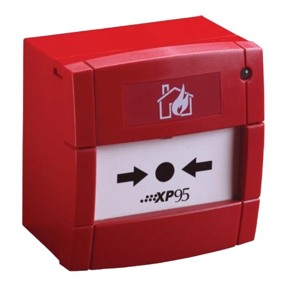
General
The XP95 Manual Call Point (EN54) is available in two versions:
–
–
Installation
1.
Fit the backbox (Fig 1) to the wall.
2.
Run the cables from the loop into the backbox and connect them to the terminal
blocks as shown in Fig 2. Ensure that functional earth/screen continuity is maintained.
Screens should be connected to the yellow terminal block marked 1–4 on the black
PCB cover.
3.
If a loop continuity test is to be done, it should be carried out before securing the call
point to the backbox (step 5). Insert the continuity links supplied with the backbox (Fig
3) into the terminal blocks before testing. After testing for continuity remove the con-
nectors and store for re-use.
4.
Set the unit address on the DIL switch in accordance with the address table overleaf.
5.
Unlock the small front cover by inserting the forked key and pushing it home. Pull the
cover down and towards you and remove the deformable element. Connect the
terminal blocks as shown in Fig. 2, secure the call point to the backbox and refi t the
deformable element as required. Finally, replace the front cover in the reverse order in
which it was removed and push it up until it locks.
FIRE DETECTORS LIMITED
XP95 Manual Call Point (EN54)
Installation Guide
part no. 55100-905, non-isolated red Manual Call Point with a standard backbox
for surface wiring.
part no. 55100-908, isolated red Manual Call Point with a standard backbox for
surface wiring.
1
Advertisement

Related Manuals for Apollo XP95 series


Summary of Contents for Apollo XP95 series
- Page 1 © Apollo Fire Detectors Limited 2006 Apollo Fire Detectors Limited, 36 Brookside Road, Havant, Hampshire, PO9 1JR, UK Tel: +44 (0) 23 9249 2412 Fax: +44 (0) 23 9249 2754...
- Page 2 The XP95 Manual Call Point (EN54) is a ‘type A’ call point and is suitable for indoor use Address Setting only. For fl ush mounting, a suitable single-gang mounting box (minimum 20mm depth) is The address of the Manual Call Point is set using the DIL switch. All segments of the switch required.