Table of Contents
Advertisement
Quick Links
Product User Manual
and enterprise branch and head offices
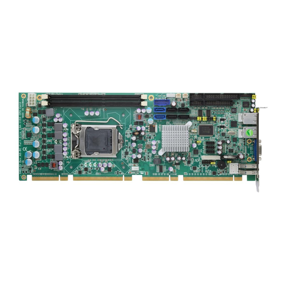
SHB120
www.enochsystems.com
1-877-722-1116
sales@enochsystems.com
Copyright © 2013 Enoch Systems, LLC, Enoch Systems and the Enoch Systems logo are trademarks or registered trademarks of Enoch Systems, LLC and/or its affiliates in the U.S. and other countries.
Third-party trademarks mentioned are the property of their respective owners. All rights reserved.
Advertisement
Table of Contents

Related Manuals for Enoch Systems SHB120


Summary of Contents for Enoch Systems SHB120
- Page 1 Copyright © 2013 Enoch Systems, LLC, Enoch Systems and the Enoch Systems logo are trademarks or registered trademarks of Enoch Systems, LLC and/or its affiliates in the U.S. and other countries. Third-party trademarks mentioned are the property of their respective owners. All rights reserved.
- Page 2 SHB120 Series ™ ™ ™ ® Intel Socket 1155 Core i7 / Core i5 / Core i3 / Processor ® PICMG 1.3 Full-Size CPU Card User’s Manual...
- Page 3 Disclaimers This manual has been carefully checked and believed to contain accurate information. Axiomtek Co., Ltd. assumes no responsibility for any infringements of patents or any third party’s rights, and any liability arising from such use. Axiomtek does not warrant or assume any legal liability or responsibility for the accuracy, completeness or usefulness of any information in this document.
-
Page 4: Esd Precautions
ESD Precautions Computer boards have integrated circuits sensitive to static electricity. To prevent chipsets from electrostatic discharge damage, please take care of the following jobs with precautions: Do not remove boards or integrated circuits from their anti-static Packaging until you are ready to install them. Before holding the board or integrated circuit, touch an unpainted portion of the system unit chassis for a few seconds. -
Page 5: Table Of Contents
Table of Contents CHAPTER 1 INTRODUCTION ......................1 Specifications ......................2 Utilities Supported ...................... 4 CHAPTER 2 JUMPERS AND CONNECTORS ................5 Board Dimension ....................... 5 Board Layout ......................6 Jumper Settings ......................7 2.3.1 COM1 Mode Select Jumpers for RS232/422/485 (JP3, JP4, JP5) ......7 2.3.2 Audio Amplifier Jumper (JP1) .................. - Page 6 Navigation Keys ....................... 37 Main Menu ....................... 39 Advanced Menu ....................... 40 Chipset Menu ......................51 Boot Menu ........................ 54 Security Menu ......................55 Save & Exit Menu..................... 56 APPENDIX A WATCHDOG TIMER ....................59 Watchdog Timer Setting ......................59 APPENDIX B PCI IRQ ROUTING ....................
- Page 7 MEMO:...
-
Page 8: Chapter 1 Introduction
CHAPTER 1 INTRODUCTION The SHB120 PICMG® 1.3 full-size Single Board Computer supports LAG1155 socket H2 for Intel® Core™ i3 Desktop Processor, Intel® Core™ i5 Desktop Processor, Core™ i7 Desktop Processor with 32nm technology and Transfer Rate 1333/1600 MHz. The board integrates Intel®... -
Page 9: Specifications
SHB120 LAG1155 Full-Size SBC User’s Manual 1.1 Specifications Intel® Core™ i3 Desktop Processor Intel® Core™ i5 Desktop Processor Intel® Core™ i7 Desktop Processor System Chipset Intel® Q77 CPU Socket LAG1155 Socket ... - Page 10 SHB120 LAG1155 Full-Size SBC User’s Manual Onboard Graphic Intel® Arrandale integrated a Graphic processing unit processor which goes with Q77 chipset with VGA, DisplayPort (co-lay with VGA) and DVI. Memory Size --Intel® DVMT 5.0 supported; preallocated memory for frame buffer option as...
-
Page 11: Utilities Supported
SHB120 LAG1155 Full-Size SBC User’s Manual Audio 10-pin 2.0 pin-header (Intel® HD Audio Digital Header) Hardware Monitoring Monitoring temperatures, voltages, and cooling fan status Watchdog Timer Reset Supported (1-255 level) Dimensions 338mm x 126mm ... -
Page 12: Chapter 2 Jumpers And Connectors
SHB120 LAG1155 Full-Size SBC User’s Manual CHAPTER 2 JUMPERS AND CONNECTORS 2.1 Board Dimension Jumpers And Connectors... -
Page 13: Board Layout
SHB120 LAG1155 Full-Size SBC User’s Manual 2.2 Board Layout Jumpers And Connectors... -
Page 14: Jumper Settings
SHB120 LAG1155 Full-Size SBC User’s Manual 2.3 Jumper Settings Proper jumper settings configure the SHB120 to meet your application purpose. We are herewith listing a summary table of all jumpers and default settings for onboard devices, respectively. Jumper Description Jumper Setting... -
Page 15: Audio Amplifier Jumper (Jp1)
SHB120 LAG1155 Full-Size SBC User’s Manual 2.3.2 Audio Amplifier Jumper (JP1) Function Jumper Setting Disable (Default) Enable 2.3.3 Clear RTC Jumper (JP8) You may need to use this jumper to clear the RTC if incorrect RTC settings. Function Jumper Setting... -
Page 16: Connectors
SHB120 LAG1155 Full-Size SBC User’s Manual 2.4 Connectors Connectors connect this board with other parts of the system. Loose or improper connection might cause problems. Make sure all connectors are properly and firmly connected. Here is a summary table shows you all connectors on the board. -
Page 17: Smbus Connector (Cn1)
SHB120 LAG1155 Full-Size SBC User’s Manual Connector Label SATA4 SATA Port 3 SATA5 SATA Port 4 SATA6 SATA Port 5 COM1 COM1 Connecter COM2 COM2 Connecter AUDIO1 Audio Connector ATX2 ATX Connecter 2.4.1 SMBUS Connector (CN1) Connector SMBUS CN1 is for SMBUS interface support. -
Page 18: Floppy Disk Port Connector (Cn4)
SHB120 LAG1155 Full-Size SBC User’s Manual 2.4.2 Floppy Disk Port Connector (CN4) The board provides a 34-pin header type connector, CN4, supporting up to two floppy drives. The floppy drives may be any one of the following types: 5.25" 360KB/1.2MB and 3.5"... -
Page 19: Internal Usb Connectors (Cn5)
SHB120 LAG1155 Full-Size SBC User’s Manual 2.4.3 Internal USB Connectors (CN5) The 19-pin standard Universal Serial Bus (USB 3.0) connectors, CN5 on this board is for installing versatile USB 3.0 interface peripherals. Signal Signal VBUS0 SSRX2- VBUS1 SSRX2+ SSRX3- SSRX3+... -
Page 20: Lan2 Led Connectors (Cn6)
SHB120 LAG1155 Full-Size SBC User’s Manual 2.4.5 LAN2 LED Connectors (CN6) Signal + 3.3V LINK_ACT LED(-) 100, Low Active +3.3V 1000, Low Active 2.4.6 LAN1 LED Connectors (CN7) Signal + 3.3V LINK_ACT LED(-) 100, Low Active +3.3V 1000, Low Active 2.4.7... -
Page 21: Dvi-D Pin Header (Cn14)
SHB120 LAG1155 Full-Size SBC User’s Manual 2.4.8 DVI-D Pin Header (CN14) This board supports a 24-pin header (CN14) for DVI-D, via DVI-D cable. Signal Signal Signal Data2- Data2+ N.C. N.C. DDC CLK DDC Data N.C. Data1- Data1+ N.C. N.C. Data0- Data0+ N.C. -
Page 22: Front Panel Connector (Cn15)
SHB120 LAG1155 Full-Size SBC User’s Manual 2.4.9 Front Panel Connector (CN15) Power LED This 3-pin connector denoted as Pin 1 and Pin 5 connects the system power LED indicator to such a switch on the case. Pin 1 is assigned as +, and Pin 5 as -. The Power LED lights up when the system is powered ON. -
Page 23: Ps/2 Keyboard, Mouse Connectors (Cn17, Cn18)
SHB120 LAG1155 Full-Size SBC User’s Manual 2.4.10 PS/2 Keyboard, Mouse Connectors (CN17, CN18) The board provides the Keyboard (CN17) / Mouse (CN18) interface with a 5-pin connecter. Signal Clock DATA No connector 5VSBY 2.4.11 External USB 3.0 Port Connectors (CN16, CN19) The 9-pin standard Universal Serial Bus (USB 3.0) port connector on the board is for the... -
Page 24: Rs232/422/485 Pin Assignment (Com1)
SHB120 LAG1155 Full-Size SBC User’s Manual 2.4.12 RS232/422/485 Pin Assignment (COM1) The serial interface for the board consists of COM1 support for RS-232 and COM1 for RS- 232/RS-422/RS-485. Signal Name RS-232 RS-422 RS-485 Data Carrier Detect (DCD) DATA- Data Set Ready (DSR) -
Page 25: Com Port Rs-232 Pin Assignment (Com2)
SHB120 LAG1155 Full-Size SBC User’s Manual 2.4.13 COM Port RS-232 Pin Assignment (COM2) COM2 Serial Port 10-pin (Box-header) Connector Pin Assignment list Signal Signal Data Carrier Detect (DCD) Data Set Ready (DSR) Receive Data (RXD) Request to Send (RTS) Transmit Data (TXD) -
Page 26: Atx 8 Pin 12V In Connector (Atx2)
SHB120 LAG1155 Full-Size SBC User’s Manual 2.4.15 ATX 8 Pin 12V IN Connector (ATX2) You can connect it to the ATX12V power supply for CPU Core Voltage. Signal +12V +12V +12V +12V 2.4.16 A CPU fan is always needed for cooling CPU heat (FAN3) The CPU fan connector FAN3 provides power to the CPU fan. -
Page 27: Ethernet Rj-45 Connectors (Lan1, Lan2)
SHB120 LAG1155 Full-Size SBC User’s Manual 2.4.18 Ethernet RJ-45 Connectors (LAN1, LAN2) The RJ-45 connectors LAN1 and LAN2 are for Ethernet. To connect the board to 100-Base-T or 1000-Base-T hub, just plug one end of the cable into LAN1 and connect the other end (phone jack) to a 100-Base-T hub or 1000-Base-T hub. -
Page 28: Parallel Port Connector (Print1) Print Port Connector
SHB120 LAG1155 Full-Size SBC User’s Manual 2.4.19 Parallel Port Connector (PRINT1) Print Port Connector This board has a multi-mode parallel port to support: Standard Mode: IBM PC/XT, PC/AT and PS/2 are compatible with bi-directional parallel port. Enhanced Mode: Enhance parallel port (EPP) is compatible with EPP 1.7 and EPP 1.9 (IEEE 1284 compliant). -
Page 29: Sata Connectors (Sata1(3.0) ,Sata2(3.0),Sata3,Sata4,Sata5,Sata6)
SHB120 LAG1155 Full-Size SBC User’s Manual 2.4.20 SATA Connectors (SATA1(3.0) ,SATA2(3.0),SATA3,SATA4,SATA5,SATA6) These SATA connectors are for high-speed SATA interface ports and they can be connected to hard disk devices. Signal SATA_TX+ SATA_TX- SATA_RX- SATA_RX+ Jumpers And Connectors... -
Page 30: Chapter 3 Hardware Installation
SHB120 LAG1156 Full-Size SBC User’s Manual CHAPTER 3 HARDWARE INSTALLATION ® Before installing the processor, please access Intel website for more detail Information. Processor Integration Video (LGA1155): http://www.intel.com/support/tw/processors/sb/CS-030860.htm . 3.1 Installing the Processor The LGA1155 processor socket comes with a cover to protect the processor. Please install the... - Page 31 SHB120 LAG1155 Full-Size SBC User’s Manual Step2 Removing the socket protective cover: Place thumb against the front edge of the protective cover and rest index finger on the rear grip to maintain control of the cover. Lift the front edge of the protective cover to disengage from the socket. Keep control of the cover by holding the rear grip with index finger.
- Page 32 SHB120 LAG1156 Full-Size SBC User’s Manual Step3 Processor installation: Lift processor package from shipping media by grasping the substrate edges. Scan the processor package gold pads for any presence of foreign material. If necessary, the gold pads can be wiped clean with a soft lint-free cloth and isopropyl alcohol.
- Page 33 SHB120 LAG1155 Full-Size SBC User’s Manual Carefully place the processor into the socket body vertically (see image below). NOTE: Tilting or roughly shifting it into place can damage socket contacts. Caution: Do not use a vacuum pen for installation.
- Page 34 SHB120 LAG1156 Full-Size SBC User’s Manual Close the socket (see image below): 1. Gently lower the load plate. 2. Make sure load plate's front edge slides under the shoulder screw cap as the lever is lowered. 3. Latch the lever under the top plate's corner tab, being cautious not to damage the motherboard with the tip of the lever.
- Page 35 SHB120 LAG1155 Full-Size SBC User’s Manual Step4 Fan heatsink handling: 1. Orientate the CPU cooling fan to fixing holes on the board. 2. Screw the CPU cooling fan onto the board. 3. Make sure the CPU fan is plugged to the CPU fan connector.
- Page 36 SHB120 LAG1156 Full-Size SBC User’s Manual Step5 Removing the processor: Open the socket: A. Disengage the load lever. B. Open the load plate. Remove the Processor package, holding along the top and bottom edges, or by using a vacuum pen.
- Page 37 SHB120 LAG1155 Full-Size SBC User’s Manual Perform Visual and Tactile verification that protective cover is properly seated in the LGA1155 Socket: *Hold cover and move gently "side to side" to feel the play within the cover and the LGA1155 Socket.
-
Page 38: Installing The Memory
SHB120 LAG1156 Full-Size SBC User’s Manual 3.2 Installing the Memory The board supports two 240-pin DDR3 DIMM memory sockets with maximum memory capacity up to 16GB. Please follow steps below to install the memory modules: Push down latches on each side of the DIMM socket. - Page 39 SHB120 LAG1155 Full-Size SBC User’s Manual MEMO: Hardware Installation...
-
Page 40: Chapter 4 Hardware Description
CPU from damages. 4.2 BIOS The SHB120 Series uses AMI Plug and Play BIOS with a single 32Mbit SPI Flash. 4.3 System Memory The SHB120 Series supports two 240-pin DDR3 DIMM sockets for a maximum memory of 16GB DDR3 SDRAMs. -
Page 41: I/O Port Address Map
SHB120 LAG1155 Full-Size SBC User’s Manual 4.4 I/O Port Address Map ™ ™ ™ ® The Intel Core i7 / Core i5 / Core i3 processors can communicate via I/O ports. There are total 1KB port addresses available for assignment to other devices via I/O expansion cards... - Page 42 SHB120 LAG1156 Full-Size SBC User’s Manual Address Devices Forward to SATA(SATA Controller) 3F8-3FF Serial port #1 (COM1) 2F8-2FF Serial port #2 (COM2) Hardware Description...
-
Page 43: Interrupt Controller (Irq) Map
SHB120 LAG1155 Full-Size SBC User’s Manual 4.5 Interrupt Controller (IRQ) Map The SHB120 Series is a 100% PC compatible control board. It consists of 16 interrupt request lines, and four out of them can be programmable. The mapping list of the 16 interrupt request lines is shown as the following table. -
Page 44: Chapter 5 Ami Bios Utility
SHB120 LAG1156 Full-Size SBC User’s Manual CHAPTER 5 AMI BIOS UTILITY This chapter provides users with detailed description how to set up basic system configuration through the AMIBIOS8 BIOS setup utility. 5.1 Starting To enter the setup screens, follow the steps below: ... - Page 45 SHB120 LAG1155 Full-Size SBC User’s Manual Left/Right The Left <Arrow> keys allow you to select a setup screen. Up/Down The Up and Down <Arrow> keys allow you to select a setup screen or sub-screen. + The Plus and Minus <Arrow> keys allow you to change the field value of a particular Plus/Minus setup item.
-
Page 46: Main Menu
SHB120 LAG1156 Full-Size SBC User’s Manual 5.3 Main Menu When the first time you enter the Setup Utility, you will be in the Main setup screen.You can always return to the Main setup screen by selecting the Main tab. There are two Main Setup options. -
Page 47: Advanced Menu
SHB120 LAG1155 Full-Size SBC User’s Manual 5.4 Advanced Menu Launch PXE OpROM Use this item to enable or disable the Boot ROM function of the onboard LAN chip when the system boots up. Launch Storage OpROM This item can set enable or disable the storage device option ROM with CF device. - Page 48 SHB120 LAG1156 Full-Size SBC User’s Manual ACPI Settings You can use this screen to select options for the ACPI Configuration, and change the value of the selected option. A description of the selected item appears on the right side of the screen.
- Page 49 SHB120 LAG1155 Full-Size SBC User’s Manual Trusted Computing You can use this screen to select options for the Trusted Computing, and change the value of the selected option. A description of the selected item appears on the right side of the screen.
- Page 50 SHB120 LAG1156 Full-Size SBC User’s Manual CPU Configuration This screen shows the CPU Configuration, and you can change the value of the selected option. Hyper-threading This item can set enable or disable for support Hyper-threading Technology. Active Processor Cores This feature controls the number of cores to enable in each processor package.
- Page 51 SHB120 LAG1155 Full-Size SBC User’s Manual SATA Configuration You can use this screen to select options for the SATA Configuration, and change the value of the selected option. A description of the selected item appears on the right side of the screen.
- Page 52 SHB120 LAG1156 Full-Size SBC User’s Manual PCH-FW Configuration The Intel IGD SWSCI OpRegion allows users to change the integrated graphic device settings. AMI BIOS Utility...
- Page 53 SHB120 LAG1155 Full-Size SBC User’s Manual AMT Configuration You can use this screen to select options for the Intel AMT Configuration, and change the value of the selected option. A description of the selected item appears on the right side of the screen.
- Page 54 SHB120 LAG1156 Full-Size SBC User’s Manual USB Configuration You can use this screen to select options for the USB Configuration, and change the value of the selected option. A description of the selected item appears on the right side of the screen.
- Page 55 SHB120 LAG1155 Full-Size SBC User’s Manual Super IO Configuration You can use this screen to select options for the Super IO Configuration, and change the value of the selected option. A description of the selected item appears on the right side of the screen. For items marked with “”, please press <Enter>...
- Page 56 SHB120 LAG1156 Full-Size SBC User’s Manual H/W Monitor This screen shows the Hardware Health Configuration, and a description of the selected item appears on the right side of the screen Smart Fan Function This item can enable or disable the Smart Fan function.
- Page 57 SHB120 LAG1155 Full-Size SBC User’s Manual Intel RC Drivers Version Detail AMI BIOS Utility...
-
Page 58: Chipset Menu
SHB120 LAG1156 Full-Size SBC User’s Manual 5.5 Chipset Menu The Chipset menu allows users to change the advanced chipset settings. You can select any of the items in the left frame of the screen to go to the sub menus: ... - Page 59 SHB120 LAG1155 Full-Size SBC User’s Manual PCH-IO Configuration USB Configuration You can use this item to set the USB Configuration. AMI BIOS Utility...
- Page 60 SHB120 LAG1156 Full-Size SBC User’s Manual System Agent (SA) Configuration It is strongly recommended that you do not modify these options unless you are an advanced user. AMI BIOS Utility...
-
Page 61: Boot Menu
SHB120 LAG1155 Full-Size SBC User’s Manual 5.6 Boot Menu The Boot menu allows users to change boot options of the system. You can select any of the items in the left frame of the screen to go to the sub menus: ... -
Page 62: Security Menu
SHB120 LAG1156 Full-Size SBC User’s Manual 5.7 Security Menu The Security menu allows users to change the security settings for the system. Administrator Password This item indicates whether an administrator password has been set. If the password has been installed, Installed displays. If not, Not Installed displays. -
Page 63: Save & Exit Menu
SHB120 LAG1155 Full-Size SBC User’s Manual 5.8 Save & Exit Menu The Save & Exit menu allows users to load your system configuration with optimal or failsafe default values. Save Changes and Exit When you have completed the system configuration changes, select this option to leave Setup and return to Main Menu. - Page 64 SHB120 LAG1156 Full-Size SBC User’s Manual Save Changes When you have completed the system configuration changes, select this option to save changes. Select Save Changes from the Save & Exit menu and press <Enter>. Select Yes to save changes.
- Page 65 SHB120 LAG1155 Full-Size SBC User’s Manual MEMO: AMI BIOS Utility...
-
Page 66: Appendix Awatchdog Timer
SHB120 LAG1156 Full-Size SBC User’s Manual APPENDIX A WATCHDOG TIMER Watchdog Timer Setting After the system stops working for a while, it can be auto-reset by the Watchdog Timer. The integrated Watchdog Timer can be set up in the system reset mode by program. - Page 67 SHB120 LAG1155 Full-Size SBC User’s Manual WDT counting re-set timer :O 2E F6 O 2F M ; M=00,01,02,…FF(See below table) IF No re-set timer : WDT time-out, generate RESET IF to disable WDT : O 2E 30 O 2F 00; Can be disable at any time...
-
Page 68: Appendix B Pci Irq Routing
SHB120 LAG1156 Full-Size SBC User’s Manual APPENDIX B PCI IRQ ROUTING ® PICMG PCI IRQ Routing Device Slot PCI Slot 0 BCDA PCI Slot 1 CDAB PCI Slot 2 DABC PCI Slot 3 ABCD PCI IRQ Routing... - Page 69 SHB120 LAG1155 Full-Size SBC User’s Manual MEMO: PCI IRQ Routing...
-
Page 70: Appendix Cconfiguring Sata For Raid Function
SHB120 LAG1156 Full-Size SBC User’s Manual APPENDIX C CONFIGURING SATA FOR RAID FUNCTION ® Configuring SATA Hard Drive(s) for RAID Function (Controller: Intel Q77) Please follow up the steps below to configure SATA hard drive(s): Install SATA hard drive(s) in your system. - Page 71 SHB120 LAG1155 Full-Size SBC User’s Manual Configuring SATA controller mode and boot sequence by the BIOS Setup You have to make sure whether the SATA controller is configured correctly by system BIOS Setup and set up BIOS boot sequence for the SATA hard drive(s) (2)-1-1 Turn on your system, and then press the Del button to enter BIOS Setup during running POST (Power-On Self Test).
- Page 72 SHB120 LAG1156 Full-Size SBC User’s Manual (2)-1-2 A list of options appears, please select RAID. Configuring SATA for RAID Function...
- Page 73 SHB120 LAG1155 Full-Size SBC User’s Manual (2)-2 Set CDROM for First Boot Device under the Boot Settings menu to boot CD-ROM after system restarts. Configuring SATA for RAID Func tion...
- Page 74 SHB120 LAG1156 Full-Size SBC User’s Manual (2)-3 Save and exit the BIOS Setup. (3) Configuring RAID by the RAID BIOS Enter the RAID BIOS setup utility to configure a RAID array. Skip this step and proceed to Section 4 if you do not want to create a RAID.
- Page 75 SHB120 LAG1155 Full-Size SBC User’s Manual (3)-2 After you press <CTRL+ I>, the Create RAID Volume screen will appear. If you want to create a RAID array, select the Create RAID Volume option in the Main Menu and press ENTER.
- Page 76 SHB120 LAG1156 Full-Size SBC User’s Manual (3)-3-1 After entering the CREATE VOLUME MENU screen, you can type the disk array name with 1~16 letters (letters cannot be special characters) in the item “Name”. (3)-3-2 When finished, press ENTER to select a RAID level. There are three RAID levels, RAID0, RAID1 and RAID5 &...
- Page 77 SHB120 LAG1155 Full-Size SBC User’s Manual (3)-4 Set the stripe block size. The KB is the standard unit of stripe block size. The stripe block size can be 4KB to 128KB. After the setting, press ENTER for the array capacity.
- Page 78 SHB120 LAG1156 Full-Size SBC User’s Manual (3)-6 When prompting the confirmation, press “Y“ to create this volume, or “N“ to cancel the creation. After the creation is completed, you can see detailed information about the RAID Array in the DISK/VOLUME INFORMATION section, including RAID mode, disk block size, disk name, and disk capacity, etc.
- Page 79 SHB120 LAG1155 Full-Size SBC User’s Manual Delete RAID Volume If you want to delete a RAID volume, select the Delete RAID Volume option in Main Menu. Press ENTER and follow on-screen instructions. Please press [ESC] to exit the RAID BIOS utility.
- Page 80 SHB120 LAG1156 Full-Size SBC User’s Manual Installing the SATA controller driver during the OS installation Now, the SATA driver disk is ready, and BIOS settings configured, you can proceed to install Windows 2000/XP onto your SATA hard drive using the SATA driver. Here is an example for Windows XP installation.
- Page 81 SHB120 LAG1155 Full-Size SBC User’s Manual (5)-2 When you see the screen below, insert the floppy disk containing the SATA driver and press “S”. Configuring SATA for RAID Func tion...
- Page 82 SHB120 LAG1156 Full-Size SBC User’s Manual (5)-3 If the Setup correctly recognizes the driver of the floppy disk, a controller menu will appear below. Use the ARROW keys to select Intel® Desktop/Workstation/Server Express Chipset SATA Raid Controller and press ENTER. Then it will begin to load the SATA driver from the floppy disk.
- Page 83 SHB120 LAG1155 Full-Size SBC User’s Manual Note: If you are installing AHCI, Please select”Intel® 7 Series/C216 Chipset Family SATA AHCI Controller”. Configuring SATA for RAID Func tion...
-
Page 84: Appendix D Iamt Settings
SHB120 LAG1156 Full-Size SBC User’s Manual APPENDIX D iAMT SETTINGS ® ® The Intel Active Management Technology (Intel iAMT) has decreased a major barrier to IT efficiency that uses built-in platform capabilities and popular third-party management and security applications to allow IT a better discovering, healing, and protection their networked computing assets. -
Page 85: Set & Change Password
SHB120 LAG1155 Full-Size SBC User’s Manual D.2 Set & Change Password You will be asked to set a password when first log in. The default password is ‘admin’. iAMT Settings... - Page 86 SHB120 LAG1156 Full-Size SBC User’s Manual You will be asked to change the password before setting ME iAMT Settings...
- Page 87 SHB120 LAG1155 Full-Size SBC User’s Manual You must confirm your new password while revising. (as Remark 1) The new password must contain: (example: !!11qqQQ) (default value)Eight characters One upper case One lower case One number One special symbol, such as ! 、 $ or ; ,...
-
Page 88: Intel® Iamt Settings
SHB120 LAG1156 Full-Size SBC User’s Manual D.3 Intel® iAMT Settings ® Select Intel AMT Configuration and press <ENTER>. iAMT Settings... - Page 89 SHB120 LAG1155 Full-Size SBC User’s Manual 1. Select Network Setup to configure AMT. (3-1) iAMT Settings...
- Page 90 SHB120 LAG1156 Full-Size SBC User’s Manual 2. Select TCP/IP to get into Network interface, and set it to ‘ENABLED’; into DHCP Mode, and set it to ‘DISABLED’ (as Remark 2) ; (3-2) iAMT Settings...
- Page 91 SHB120 LAG1155 Full-Size SBC User’s Manual iAMT Settings...
- Page 92 SHB120 LAG1156 Full-Size SBC User’s Manual 3. if DHCP Mode is disabled, e following settings: IP address iAMT Settings...
- Page 93 SHB120 LAG1155 Full-Size SBC User’s Manual Subnet mask iAMT Settings...
- Page 94 SHB120 LAG1156 Full-Size SBC User’s Manual 4. Back to Intel (R) AMT Configuration, then select Activate Network Acess and press <ENTER>. 5. Exit from MEBx after completing the iAMT settings. iAMT Settings...
-
Page 95: Iamt Web Console
SHB120 LAG1155 Full-Size SBC User’s Manual D.4 iAMT Web Console From a web browser, please type http://(IP ADDRESS):16992, which connects to iAMT Web. Example: http://10.1.40.214:16992 To log on, you will be required to type in username and password for access to the Web. - Page 96 SHB120 LAG1156 Full-Size SBC User’s Manual 3. Enter the iAMT Web. 4 Click Remote Control, and select commands on the right side. 5. When you have finished using the iAMT Web console, close the Web browser iAMT Settings...
- Page 97 SHB120 LAG1155 Full-Size SBC User’s Manual MEMO: iAMT Settings...
-
Page 98: Appendix E Picmg V1.3 Interface Definition
SHB120 LAG1156 Full-Size SBC User’s Manual APPENDIX E ® PICMG v1.3 INTERFACE DEFINITION x16 PCIe Connector A x16 PCIe Connector C Side B Side A Side B Side A USB0P USB0N USB1P USB1N WAKE# USB2P PWRBT# PME# USB2N PWRGD PSON#... - Page 99 SHB120 LAG1155 Full-Size SBC User’s Manual Mechanical Key b_PERp3 b_PERn3 REFCLK0+ REFCLK0- REFCLK1+ RSVD REFCLK1- REFCLK2+ REFCLK2- REFCLK3+ RSVD REFCLK3- REFCLK4+ REFCLK4- RSVD +3.3V +3.3V +3.3V +3.3V +3.3V +3.3V a_PETp0 +3.3V +3.3V a_PETn0 +3.3V +3.3V a_PERp0 +3.3V +3.3V a_PERn0 +3.3V +3.3V...
- Page 100 SHB120 LAG1156 Full-Size SBC User’s Manual Mechanical Key a_PETn3 a_PERp3 a_PERn3 a_PETp4 a_PETn4 a_PERp4 a_PERn4 a_PETp5 a_PETn5 a_PERp5 a_PERn5 a_PETp6 a_PETn6 a_PERp6 a_PERn6 a_PETp7 +12V +12V a_PETn7 +12V +12V a_PERp7 +12V +12V a_PERn7 +12V +12V +12V +12V +3.3V +3.3V +12V +12V +3.3V...
- Page 101 SHB120 LAG1155 Full-Size SBC User’s Manual X8 PCIe Connector B X8 PCIe Connector D Side B Side A Side B Side A +5Vaux +5Vaux INTB# INTA# INTD# INTC# a_PETp8 a_PETn8 REQ3# GNT3# a_PERp8 REQ2# GNT2# a_PERn8 PCI_RST# GNT1# a_PETp9 REQ1#...
- Page 102 SHB120 LAG1156 Full-Size SBC User’s Manual Chanical Key a_PETp14 C/BE2# a_PETn14 PCI_PRST# FRAME# a_PERp14 IRDY# TRDY# a_PERn14 DEVSEL# a_PETp15 LOCK# STOP# a_PETn15 PERR# a_PERp15 C/BE1# a_PERn15 AD14 AD12 AD15 AD10 AD13 AD09 AD11 C/BE0# AD08 +12V +12V AD06 +12V +12V...
- Page 103 SHB120 LAG1155 Full-Size SBC User’s Manual MEMO: PICMG v1.3 Interface Definition...
Need help?
Do you have a question about the SHB120 and is the answer not in the manual?
Questions and answers