AKG WMS40 User Instructions
Wireless microphone system
Hide thumbs
Also See for WMS40:
- User manual (100 pages) ,
- Service manual (26 pages) ,
- User instructions (10 pages)
Table of Contents
Advertisement
Advertisement
Table of Contents

Related Manuals for AKG WMS40


Summary of Contents for AKG WMS40
- Page 1 WMS40 User Instructions Please read the manual before using the equipment!
-
Page 2: Table Of Contents
Table of Contents Page FCC Statement ........16 1 Safety and Environment . -
Page 3: Fcc Statement
Shielded cables and I/O cords must be used for this equipment to comply with the relevant FCC regulations. Changes or modifications not expressly approved in writing by AKG Acoustics may void the user’s authority to operate this equipment. This device complies with Part 15 of the FCC Rules. Operation is subject to the following two con- ditions: (1) this device may not cause harmful interference, and (2) this device must accept any interference received, including interference that may cause undesired operation. -
Page 4: Unpacking
2 AA size 1.5 V dry batteries Please check that the packaging contains all system components as listed above. If anything is missing, please contact your AKG dealer. RMU 60 19” rack mounting kit for 2 SR 40 receivers 2.3. Optional CH 40 plastic carrying case for one complete WMS 40 system. -
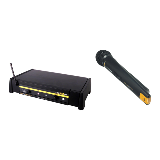
Page 5: Ht 40 Handheld Transmitter
The microphone element permanently mounted on the transmitter is acoustically identical to the D 880 vocal microphone from AKG. This microphone features a built-in wind and pop filter to reduce wind and breath noise and provides low handling noise sensitivity, high gain before feedback, and brilliant sound quality. -
Page 6: Color Code Table
Guitar Cable C 417 L (optional) C 420 L C 444 L The MKG/L guitar cable from AKG lets you connect an electric guitar, electric bass, or remote keyboard to the bodypack transmitter. 2.6.4 Optional CB 40 bag Accessory Frequency Color 2.7 Color Code... -
Page 7: Setting Up
3 Setting Up Important: Prior to setting up your WMS 40, check that the transmitter and receiv- er are tuned to the same frequency. The easiest way to do this is to compare the color codes on the transmitter and receiver. 3.1 Placing the Reflections off metal parts, walls, ceilings, etc. -
Page 8: Connecting The Receiver To An Amplifier
3 Setting Up mixer. Turn the VOLUME control (3) on the receiver all the way CCW to set the receiver output to microphone level. B. Use a standard 1/4” jack cable to connect the LINE OUT jack (8) on Refer to fig. 8b. the receiver rear panel to an unbalanced 1/4”... -
Page 9: Setting Up The Handheld Transmitter
The PT 40 bodypack transmitter has been designed primarily for use Bodypack with the C 417 L, C 420 L, and C 444 L microphones from AKG. If you Transmitter wish to connect other microphones from AKG or other manufacturers 3.10.1 Connecting a... -
Page 10: Replacing The Handheld Transmitter Color Code Clip
3 Setting Up 4. Set the on/off switch (18) to “ON” to switch power to the transmitter 5. Switch power to the receiver and your sound system or amplifier on. 6. Play your instrument and set the levels on your mixer or amplifier referring to the appropriate instruction manual or by ear. -
Page 11: C 417 L Lavalier Microphone
4 Microphone Technique 4.1.2 Angle of Sing to one side of the microphone or above and across the micro- Incidence phone’s top. This provides a well-balanced, natural sound. If you sing directly into the microphone, it will not only pick up Refer to fig. -
Page 12: Cleaning
5 Cleaning Use a soft cloth moistened with water to clean the receiver and trans- 5.1 Surfaces mitter surfaces. 1. Unscrew the wire-mesh cap of the handheld transmitter CCW and 5.2 HT 40 Internal remove the wire-mesh cap from the transmitter. Windscreen 2. -
Page 13: Specifications
6 Troubleshooting Problem Possible Cause Remedy Distortion. 1. (Bodypack transmitter 1. Turn GAIN control down or only:) GAIN control is set up just enough to stop the too high or too low. distortion. 2. Interference from other 2. Switch off interference wireless systems, TV, radio, sources or defective appli- CB radios, or defective... - Page 14 WMS 40 Fig. 3 Fig. 4 Fig. 5 SR 40 PT 40 Wireless Microphone System HT 40 Fig. 1 Fig. 11 PT 40 MUTE Fig. 10 Fig. 11 HT 40 Fig. 2 2 x 1.5V – Fig. 13 Fig. 8a 2 x 1.5V Fig.
Need help?
Do you have a question about the WMS40 and is the answer not in the manual?
Questions and answers