Table of Contents
Advertisement
Quick Links
Advertisement
Table of Contents

Related Manuals for Sokkia GSR2700 ISX


Summary of Contents for Sokkia GSR2700 ISX
- Page 1 GNSS Receiver System GSR2700 ISX Operations Manual...
- Page 3 GNSS Receiver System Tplljb GSR2700 ISX Operations Manual...
-
Page 4: Copyright Notice
WEEE Notice If you purchased your GSR2700 ISX in Europe, you must return it to your dealer or supplier at the end of its life. The objectives of the European Community's environment policy are, in particular, to preserve, protect and improve the quality of the environment, protect human health and utilize natural resources prudently and rationally. -
Page 5: Table Of Contents
Contents Chapter 1 Introduction About the GSR2700 ISX...........1 Features ..............2 System Components ..........3 Document Conventions ..........6 Usage Cautions ............6 Finding More Information..........8 Obtaining Technical Assistance .......8 Chapter 2 GSR2700 ISX Components Enclosure Features ..........9 Ports ...............11 2.2.1 Antenna port............12 2.2.2... - Page 6 Typical RTK rover setup ........39 5.3.2 Typical RTK base setup ........42 5.3.3 Typical static setup ..........46 Chapter 6 Powering the GSR2700 ISX Turning the System On and Off ......48 Power Source............48 6.2.1 Internal batteries..........48 6.2.2 External power source........
- Page 7 Appendix D Installing the USB Driver Downloading the USB Driver ........75 Installing the Driver ..........75 D.2.1 Windows XP driver installation ......76 D.2.2 Windows 2000 driver installation......77 Configuring USB COM Ports ........78 Windows Driver Signing .........79 Glossary Index GSR2700 ISX Operations Manual...
- Page 8 Tables GSR2700 ISX Features............2 Standard Component Descriptions ........5 Optional Component Descriptions........6 Receiver Underside Descriptions ........10 Port Descriptions .............. 11 Battery Operation Times ..........14 Display Panel Components ..........19 Power Button Functions ........... 21 Battery Life Gauge Indicators ........... 24 Satellite Tracking Gauge Indicators .........
- Page 9 Tables Hours of Storage with 64 MB Logging Capacity ....59 GSR2700 ISX Technical Specifications......60 GSR2700 ISX Operations Manual...
- Page 10 Figures Standard RTK Rover System Components......4 Standard RTK Base System Components ......4 Optional System Components ........... 5 GSR2700 ISX ..............9 Receiver Underside View ..........10 Ports ................. 11 Internal Radio Antenna............. 12 Antenna Radome ............. 16 Display Panel Components ..........19 Power Button Functions ...........
-
Page 11: Chapter 1 Introduction
Bluetooth-enabled devices (for example, your handheld data collector), providing a completely cable-free option. For differential correction transmission flexibility, the GSR2700 ISX uses either an internal UHF or GSM/GPRS radio. It also offers the innovative feature of voice messages to indicate receiver status during field operation. -
Page 12: Features
Introduction Chapter 1 Features The GSR2700 ISX is capable of the following modes of operation: • RTK rover operation • RTK base operation • Navigation • Differential GPS • Static post-processing • Stop-and-go kinematic post-processing The GSR2700 ISX features are summarized in Table 1. For detailed technical information, see Appendix A, Technical Specifications, page 60. -
Page 13: System Components
Computed Data: Position, speed, direction, & clock offset = 20 Measured Data (Observations): Pseudorange & carrier phase = 20 System Components When you receive your GSR2700 ISX system, ensure that you have received all of the components for your specific configuration (rover or base). -
Page 14: Standard Rtk Rover System Components
Introduction Chapter 1 Figure 1: Standard RTK Rover System Components GPS Receiver System GSR2700 IS Operations Manual Figure 2: Standard RTK Base System Components GPS Receiver System GSR2700 IS Operations Manual GSR2700 ISX Operations Manual... -
Page 15: Standard Component Descriptions
Tape measure Manual Hard case Figure 3 illustrates optional components that you may also want to use with your system. Components are described in Table 3, Optional Component Descriptions, page 6. Figure 3: Optional System Components GSR2700 ISX Operations Manual... -
Page 16: Document Conventions
Never disconnect the radio antenna while the internal radio is still powered. Disconnecting the antenna while the receiver is on may cause irreparable damage to the internal circuitry of your radio, particularly when the radio is transmitting information. GSR2700 ISX Operations Manual... - Page 17 Introduction Chapter 1 CAUTION • If travelling with or shipping the GSR2700 ISX by air, ensure that you remove the tripod or survey pole, or any other mount component from the socket on the receiver’s underside (Figure 5, Receiver Underside View, page 10).
-
Page 18: Finding More Information
(if applicable). • A descriptive and concise explanation of the problem. For a list of SOKKIA worldwide offices, see the list at the back of this manual. GSR2700 ISX Operations Manual... -
Page 19: Chapter 2 Gsr2700 Isx Components
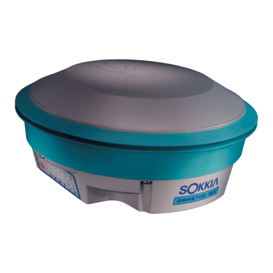
Enclosure Features The top of the GSR2700 ISX encloses the antenna and radome, surrounded by a shock-absorbing protective bumper. One side of the receiver shows the radio antenna port and the display panel (see Figure 4), which you can use to control and monitor the system. -
Page 20: Receiver Underside Descriptions
Phase center offset label (antenna specifications). CAUTION If travelling with or shipping the GSR2700 ISX by air, remove the tripod or survey pole from the survey mount socket (see #1 in Figure 5). This will prevent any damage that can occur if the pressure vent inside the receiver is blocked. -
Page 21: Ports
GSR2700 ISX Components Chapter 2 Ports The GSR2700 ISX features an external power input port, two communication ports, and an antenna connector port for the internal radio. All ports are located on the underside of the enclosure and are protected from dust and water by covers. -
Page 22: Antenna Port
Power input port 2.2.1 Antenna port The GSR2700 ISX has an external TNC antenna connector for an internal UHF radio antenna or a GSM/GPRS radio antenna (if installed in the receiver body). Figure 7 shows a view of the receiver with the UHF radio antenna attached. For more information about the internal radio, see Section 2.7, Internal... -
Page 23: Communication Ports
Section 6.2, Power Source, page 48. Cables To prevent damage to both the GSR2700 ISX and the cables, each GSR2700 ISX cable connector is keyed to ensure that the cable can be inserted in only one way. In addition, connectors have a latching mechanism that requires careful insertion and removal from ports. -
Page 24: Batteries
CAUTION Do not pull directly on the cable. Batteries The GSR2700 ISX incorporates two internal custom Li-Ion battery packs. Table 6 provides approximate operational run times for the batteries, based on the setup and survey methods you use. Table 6: Battery Operation Times Internal batteries will power the unit continuously for <X>... -
Page 25: Memory
Section 6.2, Power Source, page 48. Memory The GSR2700 ISX comes with 64 MB of internal memory to support post-processing applications. For information about how many hours of data can be stored in memory, see Section 7.4, Data Storage Capacity, page 58. -
Page 26: Antenna
GSR2700 ISX Components Chapter 2 Antenna The GSR2700 ISX features the upgraded and integrated antenna (see Figure 8), which is capable of GPS and GLONASS measurement tracking. It also includes Pinwheel™ technology. Figure 8: Antenna Radome The phase center offset label is located on the underside of the receiver (see Figure 5, Receiver Underside View, page 10). -
Page 27: Internal Radio
Chapter 2 Internal Radio Depending on your particular system configuration, the GSR2700 ISX may include an internal UHF or GSM/GPRS radio for transmitting or receiving differential corrections for RTK applications. The radio antenna connects on the underside of the receiver (for details, see Section 2.2.1, Antenna port, page 12). -
Page 28: Display Panel
GSR2700 ISX Components Chapter 2 Display Panel The GSR2700 ISX has an easy-to-use display panel with single- button operation and LED display indicators that give you a view of your system status. For details about the display panel features and how to use them, see Chapter 3, Display Panel Operations, page 19. -
Page 29: Chapter 3 Display Panel Operations
Display Panel Chapter 3 Operations The GSR2700 ISX LED display panel provides receiver status information, including battery life, memory available, satellites tracked, and port and radio activity. In addition to the visual display, a series of voice messages or sounds alert you to receiver status and event conditions. -
Page 30: Power Button
Ensure that you firmly hold the power button for the entire duration that is required to perform the action you want. The power button functions are illustrated in Figure 10, Power Button Functions, page 21 and summarized in Table 8, Power Button Functions, page 21. GSR2700 ISX Operations Manual... -
Page 31: Power Button Functions
Note: It is normal for the receiver health indicator LEDs to illuminate during startup. Turn off Press the button for 3 seconds and/or until you hear the “Power Off” message or sound, and the top three battery life gauge LEDs illuminate. GSR2700 ISX Operations Manual... - Page 32 25 seconds, so that the receiver simply returns to normal operation. To delete individual files from the memory, use a data collector or SOKKIA software on your PC. Disregard When you hold the button longer than 25 seconds and you hear the “Continue...
-
Page 33: Gauges
Display Panel Operations Chapter 3 Gauges The GSR2700 ISX display panel features four gauges to provide information about the following: • Battery life and charging status • Satellites currently being tracked (page 24) • Memory available (page 25) • Time indicating the period of continuous data of sufficient... -
Page 34: Satellite Tracking Gauge
For a satellite to be counted as used, it must have a healthy signal and be above the elevation mask, and the receiver must have achieved lock (both code and carrier). GSR2700 ISX Operations Manual... -
Page 35: Memory Gauge
Table 11 summarizes the values indicated by the 1 – memory gauge LEDs. Table 11: Memory Gauge Indicators Available Memory (%) 80 to 100 60 to 80 40 to 60 20 to 40 0 to 20 GSR2700 ISX Operations Manual... -
Page 36: Timer Gauge
Performance of the indicator depends on quality GNSS data being observed at other receivers (no obstructions, same satellites, low multipath, etc.). If you are uncertain about the quality of the data collected, log data for a longer period of time. GSR2700 ISX Operations Manual... -
Page 37: Timer Gauge - Baseline Length Mode
30 or more minutes 20 or more minutes 10 or more minutes NOTE For successful post-processing, it is assumed that there are no adverse environmental conditions and that you have a data logging interval of 10 seconds. GSR2700 ISX Operations Manual... -
Page 38: Status Indicators
Display Panel Operations Chapter 3 Status Indicators The GSR2700 ISX display panel features status indicators on the panel that provide the following information: • Receiver health (page 28) • COM port communication status (page 30) • Wireless communication status (page 31) •... -
Page 39: Temperature Issues
Table 15: Voltage Issues If you see the sequence shown in Table 16, then the receiver firmware has not been loaded with a valid authorization code. Contact your SOKKIA distributor with your receiver serial number to obtain the code. Table 16: Firmware Issues If an error condition persists, take the following steps: Turn the receiver off for a few minutes. -
Page 40: Com Port Communication Status
LEDs. Table 17: COM Ports Communication Status LEDs State Status Description Illuminated Data is being received by the GSR2700 ISX through the COM port. Dark No data is being received through the COM port. Green Illuminated Data is being transmitted from the GSR2700 ISX through the COM port. -
Page 41: Wireless Communication Status
Data is being transmitted from the receiver through the Bluetooth port. Dark No data is being transmitted through the Bluetooth port. If data is simultaneously being transmitted and received, both transmit and receive LED indicators are illuminated. During GSR2700 ISX Operations Manual... -
Page 42: Internal Radio Status
Bluetooth LED on the display panel will stop flashing. To restore power to the GSR2700 ISX Bluetooth port, power cycle the GSR2700 ISX (i.e., turn off the receiver, then turn it back on). For details about the wireless communication device, see Section 2.8, Wireless Communication, page 17. -
Page 43: Internal Radio Status Leds
Power is being provided to the internal radio device (including GSM or UHF). Dark The internal radio is powered off. Flashing Data is being received by the GSR2700 ISX through the internal radio device. Dark No data is being received through the internal radio device. -
Page 44: Audible Annunciator
Chapter 4 Audible Annunciator The GSR2700 ISX receiver is equipped with an audible annunciator, which issues a series of voice messages or sounds to alert you to the system status and event conditions. NOTE Your receiver is preconfigured with either voice messages or sounds at a preset volume. - Page 45 A file is open for data logging continuous on the receiver, but the memory is full and new data can no longer be stored. Bluetooth Connected A Bluetooth connection has once been established with another device. GSR2700 ISX Operations Manual...
- Page 46 A fixed-integer RTK solution once has been lost. Epoch Recorded An epoch of raw GNSS data once has been recorded to file (i.e., the receiver has been configured to record data to the internal CompactFlash memory card). GSR2700 ISX Operations Manual...
-
Page 47: Chapter 5 System Setup
Chapter 1, Finding More Information, page 8 and Chapter 7, Collecting Data, page 53). If you plan to use the GSR2700 ISX to configure the receiver or to control the survey, connect a data collector. (A data collector is not always necessary; for example, if you are using the receiver as an RTK base or in a static survey). -
Page 48: Setting Up At The Office
Chapter 5 Setting Up at the Office An office setup can be used to configure the GSR2700 ISX or to transfer collected data from the receiver to a PC. The GSR2700 ISX supports the transfer of data from the receiver’s memory to a PC in the following ways: •... -
Page 49: Setting Up For Field Operations
System Setup Chapter 5 Press the power button. The GSR2700 ISX will initialize and issue a “Receiver Ready” message (or matching sound) when complete. If you are using a Bluetooth connection, connect from the PC to the receiver. Communicate with the GSR2700 ISX. For example, you can... -
Page 50: Rtk Rover Setup Components
Figure 11 illustrates a typical rover setup: Figure 11: Typical RTK Rover Setup Table 21: RTK Rover Setup Components Number Description Internal radio antenna (UHF or GSM/GPRS) GSR2700 ISX receiver Quick release Data collector Range pole Data collector mounting bracket GSR2700 ISX Operations Manual... - Page 51 System Setup Chapter 5 To set up the receiver as an RTK rover: Mount the GSR2700 ISX on the pole. Connect the internal radio antenna to the receiver’s antenna port (see Section 2.7, Internal Radio, page 17). CAUTION • Always ensure that the radio antenna is properly connected to your receiver before turning the unit on.
-
Page 52: Typical Rtk Base Setup
Typical RTK base setup A typical RTK base station setup consists of a tripod and the GSR2700 ISX receiver with an internal UHF or GSM/GPRS radio. The receiver should also be loaded with the appropriate POWERUP configuration (see Table 25, POWERUP Configurations, page 56). -
Page 53: Rtk Base Setup Components (Internal Radio)
Figure 13: Typical RTK Base Setup (external radio) CAUTION A radio antenna that is attached to a high- powered external radio (power >5W) should be located a minimum distance of 1 m from the GSR2700 ISX receiver. GSR2700 ISX Operations Manual... -
Page 54: Rtk Base Setup Components (External Radio)
Tripod Radio antenna mount (and/or adapter) Radio antenna To set up the GSR2700 ISX as an RTK base, follow the steps below: Mount the GSR2700 ISX on the tripod. If you are using the internal radio, connect the internal radio antenna to the receiver’s antenna port (see Section 2.7,... - Page 55 Table 10, Satellite Tracking Gauge Indicators, page 25). To verify that corrections are being transmitted: • Check the internal radio status LED indicator: the LED will flash green (see Table 19, Internal Radio Status LEDs, page 33). - or - GSR2700 ISX Operations Manual...
-
Page 56: Typical Static Setup
SDR+ User's Guide. 5.3.3 Typical static setup To set up the GSR2700 ISX for static surveys, the receiver should be loaded with the appropriate POWERUP configuration (see Table 25, POWERUP Configurations, page 56). The receiver is typically mounted on a tripod. -
Page 57: Static Setup Components
Gauge Indicators, page 25). To verify the receiver’s occupation status or to verify that you have collected enough data to get a fixed position on the baseline, check the Timer gauge (see Section 3.2.4, Timer gauge, page 26). GSR2700 ISX Operations Manual... -
Page 58: Chapter 6 Powering The Gsr2700 Isx
If you turn off the GSR2700 ISX while it is logging data to the memory, the receiver will save and close any open files before turning off. -
Page 59: External Power Source
Powering the GSR2700 ISX Chapter 6 6.2.2 External power source In addition to using the internal batteries, the GSR2700 ISX can also be powered using an external battery according to the recommendations in this section. NOTE If you want to power your receiver while driving a vehicle, use a DC to AC inverter that meets the input specifications as detailed in Appendix A, Technical Specifications, page 60. -
Page 60: Powering Peripheral Devices
COM1 would not usually provide power. If the peripheral devices attached to the GSR2700 ISX draw too much power from the battery output, the receiver will limit the available current to prevent damage to the receiver. Once the excessive load is removed, normal operation of the system will resume. -
Page 61: Insufficient Power
If both of the internal batteries or the external power input voltage are below minimum operating parameters (in other words, if the GSR2700 ISX experiences drained batteries or power failure), the receiver will turn off and become inactive. If this happens, you will not be able to turn the receiver back on until you restore sufficient power. -
Page 62: Charging The Internal Batteries
LED stops flashing when charging is complete. CAUTION • The supplied AC Adapter is designed specifically for charging the GSR2700 ISX. DO NOT use any other charger with the GSR2700 ISX. • DO NOT use the AC Adapter outdoors for field operations with the GSR2700 ISX. -
Page 63: Chapter 7 Collecting Data
Chapter 7 Collecting Data You can collect data with the GSR2700 ISX in several ways and define the type of information stored during data collection. How Data is Stored The most basic activity you will perform using your GSR2700 ISX is collecting raw data, which are recorded as time-tagged measurements in your raw data file. -
Page 64: Receiver Logging To Internal Memory With Pow
When you turn on the GSR2700 ISX, the receiver will use its preset POWERUP configuration until the controller takes control. Commands sent to the receiver through the data collector will supersede the POWERUP configuration on the receiver. - Page 65 • The wireless communication power settings. 7.2.2.2 Default POWERUP configuration The GSR2700 ISX initially operates on a default POWERUP configuration, which is always present on the receiver unless you remove it using the POWERUP Configuration Manager. Your receiver is typically preset with one of five possible default POWERUP configurations.
-
Page 66: Powerup Configurations
(secs) Differential RTCM RTCA RTCA RTCA correction format 18/19 Default base ID AAAA AAAA AAAA Correction transmit interval (secs) Base position transmit interval (secs) Corrections to internal radio if present Corrections to external COM2 GSR2700 ISX Operations Manual... -
Page 67: Data File Naming
Only one POWERUP configuration can reside on the receiver at one time. When you transfer a POWERUP configuration to the GSR2700 ISX, it replaces the existing configuration on the receiver. When you reset the receiver back to factory defaults, any... -
Page 68: Data Storage Capacity
E), the file name would be 0087025E.PDC. A conflict between an auto-generated file name and an existing file name is unlikely, but if it occurs, the GSR2700 ISX resolves it by creating a file name as follows: the first character is a tilde (~), followed by a 7-digit random number and a .PDC extension (for... -
Page 69: Resetting The Receiver
Pressing the power button for between 20-25 seconds deletes all the files from the receiver’s memory (see Section 3.1, Power Button, page 20). The receiver will audibly indicate that the files have been deleted (see Chapter 4, Audible Annunciator, page 34). GSR2700 ISX Operations Manual... -
Page 70: Appendix A Technical Specifications
Technical Appendix A Specifications Table 28 summarizes the GSR2700 ISX specifications. NOTE Specifications are subject to change without notice. Table 28: GSR2700 ISX Technical Specifications Physical Size (diameter x 22.5 cm x 10.5 cm (8.9 in x 4.1 in) height) Weight (internal radio) 1.8 kg (3.9 lbs) - Page 71 Technical Specifications Appendix A Table 28: GSR2700 ISX Technical Specifications (continued) Interface Operation Single-button operation for power, receiver reset and clear memory Display LED display status indicators Status Indicators Power, battery life, satellites tracked, available memory, occupation timer, communications status Audible notifications for receiver status information;...
- Page 72 Technical Specifications Appendix A Table 28: GSR2700 ISX Technical Specifications (continued) Position Accuracy Static H: 3.0 mm + 0.5 ppm V: 10.0 mm + 1 ppm Rapid Static H: 5.0 mm + 1 ppm V: 10.0 mm + 1 ppm Kinematic, Stop-and-Go H: 10.0 mm + 1 ppm...
- Page 73 Current 1 A (max) Power Management Once the internal batteries are completely discharged, the GSR2700 ISX becomes inactive. Normal operations resume when you charge the internal batteries or when you connect an external power source to the system. For more details, see Section 6.2.2, External power source, page 49.
- Page 74 Technical Specifications Appendix A Table 28: GSR2700 ISX Technical Specifications (continued) Serial Electrical Format EIA/TIA-232-E Data Links Internal UHF 380-470 MHz (Tx/Rx) Selectable 10 mW to 1 W Internal GSM/GPRS 850/1800 MHz or 900/1900 MHz band External UHF Yes. Satel or Pacific Crest Serial EIA/TIA-232-E •...
- Page 75 The GSR2700 ISX can acquire and track satellites while undergoing vibration profiles as specified in the test standards listed above. It assumes that C/No > 45 db-Hz and that the GSR2700 ISX is in high-dynamics mode. a. Storage temperature range is recommended to maintain shelf life of internal batteries.
-
Page 76: Appendix B Allegro Cx Bluetooth Connections
In the Bluetooth Device Discovery wizard, select Next>. Select Any Bluetooth device and then select Next>. The device will search for devices and display a list of the devices found. Select the GSR2700 ISX <serial number> check box and then select Next>. GSR2700 ISX Operations Manual... - Page 77 NOTE If you plan to use your data collector with more than one GSR2700 ISX receiver, you may want to skip setting it as a favourite. Otherwise, the device you set as your favourite will always be selected by default.
- Page 78 14. Select <OK>. You return to the Device Manager list screen. Receiver COM ports 15. To view ports available on the receiver that control the data collection or correction reception methods, select Device | Properties. GSR2700 ISX Operations Manual...
-
Page 79: Gsr2700 Isx
Please refer to the SDR+ User’s Guide for more information about configuring the receiver with SDR+ software. If you are going to use the GSR2700 ISX to receive RTK corrections (from another Bluetooth-enabled device), you will need to select “XCOM2” as the receiver serial port when you establish communications. -
Page 80: Appendix C Configuring Satel Radios
Both radios provide a TNC connector on the top of the unit, to which an antenna can be directly connected. Both radios also provide an RS-232 serial port on the bottom of the unit, to use for communication with the receiver. GSR2700 ISX Operations Manual... -
Page 81: C.2 Radio Cables
Configuring Satel Radios Appendix C C.2 Radio Cables The Epic and 3ASd radios connect to the GSR2700 ISX using a cable connection. The Epic radio uses a “Y” cable with a LEMO connector and an SAE power connector at the receiver end. This allows you to power the radio from an external power source, so you don’t... -
Page 82: C.4 Setting The Transmitter Output Power
Select Set by pressing the Select button Press the Cancel/Back button to go back to the Setup main menu. Press the Cancel/Back button to exit Setup. To save your changes, select “YES” by pressing the Select button GSR2700 ISX Operations Manual... -
Page 83: C.5 Turning On Error Correction
A repeater is a radio that is configured to receive data (RX) on a given frequency and then send the same data out (TX) on the same frequency. This achieves much longer ranges for the RTK baseline as a whole. GSR2700 ISX Operations Manual... - Page 84 “ON” and “OFF”. When “ON” is displayed, press the Cancel/Back button go back to the Setup main menu. Press the Cancel/Back button to exit Setup. To save your changes, select “YES” by pressing the Select button GSR2700 ISX Operations Manual...
-
Page 85: Appendix D Installing The Usb Driver
To download the USB driver: Go to the POINT website at www.point-inc.com and select Support. Click GSR2700 ISX, then click the link to the current USB driver. Click the link for the .zip file to start the file download. Once you’ve downloaded the .zip file, extract its contents to a folder you can easily find later. -
Page 86: Windows Xp Driver Installation
10. After installing the USB driver, Windows will detect each of the receiver’s three virtual COM Ports (USB1, USB2, and USB3) and will begin to initialize them. As each port is detected, the Found New Hardware wizard will start. GSR2700 ISX Operations Manual... -
Page 87: Windows 2000 Driver Installation
The new COM ports corresponding to the receiver's USB1, USB2, and USB3 ports will be numbered sequentially following the existing ports in the PC, and are ready to use with any application that communicates with the receiver's serial COM ports. GSR2700 ISX Operations Manual... -
Page 88: D.3 Configuring Usb Com Ports
USB virtual COM port using the Configure USB Virtual Serial Ports utility. To open the utility, select Start | Program Files | Sokkia. To change the COM port number assignment, click <Configure…>. In the Configure Ports dialog box, modify the number of each USB virtual port, then click <OK>. -
Page 89: D.4 Windows Driver Signing
Click <OK> to accept the new policy. Click <OK> to close the System Properties dialog box. Disconnect the receiver USB cable, reconnect it, then follow the installation instructions in Section D.2, Installing the Driver, page 75. GSR2700 ISX Operations Manual... -
Page 91: Glossary
(also known as integrated Doppler). Circular Error Probable (CEP)—The radius of a circle, centered at your true location, that contains 50% of the individual position measurements made. GSR2700 ISX Operations Manual... - Page 92 Ephemeris—A set of satellite orbit parameters used by a GNSS receiver to calculate precise GNSS satellite positions and velocities. The ephemeris is used in the determination of the position solution and is updated periodically. Available as “broadcast ephemeris” or as post-processed “precise ephemeris”. GSR2700 ISX Operations Manual...
- Page 93 International Atomic Time (IAT) = GPS + 19.000 sec. The IAT and Universal Time Coordinated (UTC) are closely related. The difference is that UTC contains leap seconds to adjust for changes in the Earth’s rotation. See UTC. GSR2700 ISX Operations Manual...
- Page 94 P-code. A C/A code will be available on the L2 frequency in the future. L-Band—The range of radio frequencies that includes the GPS L1 and L2 carrier frequencies and the OmniSTAR satellite signals. Mask angle—See Elevation mask angle. GSR2700 ISX Operations Manual...
- Page 95 RMS—Root-Mean Square. A statistical measure of the scatter of computed positions about a “best fit” position solution. RTCA—Radio Technical Commission for Aeronautics. An organization that developed and defined a message format for differential positioning. GSR2700 ISX Operations Manual...
- Page 96 This specification varies with the operating state of the receiver, the length of time since the last position fix, the location of the last fix, and the specific receiver design. GSR2700 ISX Operations Manual...
- Page 97 Earth. It is often used as a reference on a worldwide basis, while other coordinate systems are used locally to provide a better fit to the Earth in a local region. GSR2700 ISX Operations Manual...
-
Page 99: Index
9 collecting data, 53–59 epoch recorded, 36 color coding, 13 erasing the memory, 22 COM ports, 13, 30 error conditions, 28 communication error correction, external radios, 73 ports, 13, 30–32 external battery, 49 GSR2700 ISX Operations Manual... - Page 100 13, 50 tors overview, 1 insufficient power, 51 internal radios about, 17 peripheral devices, powering, 13, 50 antenna, 12, 17 phase center offset, 10 cautions for use, 6 ports status indicators, 32–33 antenna, 12, 17 GSR2700 ISX Operations Manual...
- Page 101 22, 59 radio, 72 rover troubleshooting, 28–30 external radio, 70 setup, 39–41 system components, 4 UHF radio, 17 usage cautions, 6 USB communication, 13, 38, 75–79 Satel radios, configuring, 70–74 GSR2700 ISX Operations Manual...
- Page 102 See audible annun- ciator volume, setting, 34 warning conditions, 28 wireless communication about, 1, 17 antenna, 10 COM activity connection, 32 configuring, 66–69 connection established lost, 35–36 re-establishing a connection, 32 status indicators, 31–32 GSR2700 ISX Operations Manual...
-
Page 103: Ce Declaration Of Conformity
POINT, Inc. Kansas City • 16900 W. 118th Terr. Olathe, KS 66061 • PH 1-913-492-7585 POINT, Inc. Calgary • 1120 68th Avenue NE Calgary, Alberta, Canada T2E 8S5 • PH 1-403-295-4981 CE DECLARATION OF CONFORMITY... - Page 105 SOKKIA has been delivering superior products, sales and support around the world since 1920. You can find an authorized SOKKIA representative in nearly every region of the globe. For customer service, we recommend that you contact your local SOKKIA distributor. If you need assistance locating a distributor in your area, please contact the appropriate SOKKIA worldwide office listed below.
- Page 106 E-mail: pointaustralia@bigpond.com SOKKIA Pty. Ltd. Rydalmere, New South Wales, Australia Ph: +61-2-9638-2400 Fax: +61-2-9638-2200 E-mail: sales@sokkia.com.au Web: www.sokkia.com.au SOUTH KOREA SOKKIA Korea Co. Ltd. Seoul, Republic of Korea Ph: +82-2-514-0491 Fax: +82-2-514-0495 E-mail: sokkia@sokkia.co.kr Web: www.sokkia.co.kr TAIWAN Meridware Co., Ltd.
Need help?
Do you have a question about the GSR2700 ISX and is the answer not in the manual?
Questions and answers