Table of Contents
Advertisement
Quick Links
Advertisement
Table of Contents

Related Manuals for Sokkia GCX3


Summary of Contents for Sokkia GCX3
- Page 1 GNSS Receiver Operator’s Manual...
- Page 2 GCX3 GNSS Receiver Operator’s Manual Part Number 1016293-01 Revision B © Copyright Sokkia February, 2017 ® All contents in this manual are copyrighted by Sokkia . All rights reserved...
-
Page 3: Table Of Contents
GCX3 Features ........ - Page 4 Resetting the Receiving (Clearing) NVRAM ......29 Clearing NVRAM Using Sokkia Receiving Utility (SRU) ....29 System Setup .
- Page 5 Cannot Establish a Bluetooth Connection ......43 Sokkia Receiver Utility (SRU) Problems ......44 SRU Cannot Connect to Receiver .
-
Page 6: Preface
The materials available in this Manual (the “Manual”) have been prepared by Topcon Positioning Systems , Incorporated. (“TPS”) for owners of Sokkia products, and are designed to assist owners with the use of the receiver and its use is subject to these terms and conditions (the “Terms and Conditions”). -
Page 7: Manual Conventions
Terms or Conditions. You agree to destroy the Software and manual upon termination of the use of the receiver. All ownership, copyright and other intellectual property rights in and to the Software belong to TPS. If these license terms are not acceptable, return any unused software and manual. -
Page 8: Introduction
The GCX3 includes Sokkia’s exclusive Long-Range Bluetooth Technology, which provides the perfect solution for short range job sites that require RTK communication. The GCX3 can be paired with a cellular-enabled data collector to receive corrections from an Ntrip Caster for rover operation. This setup can also be used with MAGNET Relay for a cost effective RTK base solution over long distances. -
Page 9: Acronyms And Terminology Used In This Operator's Manual
GCX3 Features The GCX3 receiver’s advanced design eliminates the need for cables during operation, allowing for a simplified setup and less parts to keep track of. The GCX3 receiver features the following: Compact, lightweight, and rugged design •... -
Page 10: Unpacking Your Receiver Kit
You can configure the GCX3 receiver in a variety of ways, depending on your project requirements. Typically, the receiver supports the following operation modes. • Static/post-processing data collection Job site RTK using Long-Range Bluetooth Technology • • Network Rover for DGPS and RTK operation •... -
Page 11: Technical Documents
MAGNET Relay, you can connect the GCX3 Cellular receiver to the Relay service (via cellular-enabled data collector) and use it as a Base for up to 10 Rovers. Contact your Sokkia dealer for more information about the Sokkia software described above. -
Page 12: Website
Website On the Sokkia website (www.sokkia.com), you can download manuals, technical documentation, training material, and various other utility software to help you set up and use the GCX3 receiver. The website also offers registration resources, training, and technical assistance. For additional information go to www.sokkia.com and select Sokkia Care. -
Page 13: Getting Acquainted
Sokkia Care tab. Cable and Adapters The GCX3 package includes a Micro-AB USB cable for power and data transfer. Table 2 describes the cable and adapters included with your receiver. All power related accessories (power adapter, Micro-AB USB cable) with the Product are provided by Topcon. - Page 14 (controller or computer) for data transfer, receiver configuration, and to a power adapter for charging the internal battery. Note: Sokkia recommends using this supplied cable with your receiver for more stable communication and charging. AC/DC Desktop Wall Adapter...
-
Page 15: Drivers
19. Memory The GCX3 is equipped with an internal, non-removable memory card that provides up to 8 GB of data storage. As data is logged to the receiver’s memory, the REC LED displays the memory capacity status. See “Recording and Memory LED (REC)” on page 14 for more information. -
Page 16: Micro-Ab Usb Port Panel
Micro-AB USB Port Panel The receiver is equipped with a Micro-AB USB port for high-speed data transfer and communication between the receiver and an external device, for charging the internal battery, and for powering the receiver with an external power supply. See “Using Internal and External Power Sources” on page 16. Figure 3: Micro-AB USB Port Panel P/N: 1016293-01 Receiver Overview... -
Page 17: Display Panel Operations
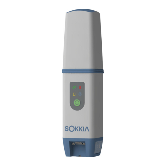
Display Panel Operations The LED display panel provides controls for receiver power and data recording. The LEDs display the status of satellite tracking, recording/memory capacity, Long-Range Bluetooth Technology connections, and battery status. Status Battery (STAT) (BATT) Recording Bluetooth® (BT) (REC) Power Button (PWR) Figure 4: LED Display Panel... -
Page 18: Power Button (Pwr)
Power Button (PWR) The green power button performs multiple functions. The duration in which the button is pressed and held determines how the receiver will function. While pressing the button, the LED Display panel indicates the selected operation for specific LEDs. Table 4. - Page 19 Table 4. Power Button Functions Press and Hold Function Description Power Button Receiver 3–10 seconds Battery LED Internal Power Only—turns solid red until Powered OFF Power Button is released. Once the Power Button is released the Battery LED is OFF. See Table 8, “Battery LED (BATT) Blink Patterns—RECEIVER IS POWERED OFF/INTERNAL BATTERY IN USE”...
-
Page 20: Receiver Status Leds
There are four receiver LEDs on the Display Panel. These LEDs display information about: GCX3 Satellite Tracking Status (STAT) • • GCX3 Recording and Memory (REC) activity and capacity, • GCX3 Bluetooth (BT) wireless connectivity status activity, • GCX3 Battery (BATT) charge level Satellite Tracking Status (STAT) LED Table 5 below describes the behavior of the Satellite Tracking Status (STAT) LED. -
Page 21: Recording And Memory Led (Rec)
Recording and Memory LED (REC) The recording and memory LED (REC) indicates if data is being written to memory and displays how much memory the receiver has available for recording. Table 6. Recording and Memory LED (REC) Blink Patterns Display Function Description GREEN... -
Page 22: Battery Led (Batt)
Battery LED (BATT) The Battery (BATT) LED indicates the remaining charge of the internal battery. When an external power source is connected to the receiver the LED turns green and begins to blink when the battery is charging. Table 8. Battery LED (BATT) Blink Patterns Display Description RECEIVER IS POWERED ON/INTERNAL BATTERY IN USE... -
Page 23: Managing Power
Depending on use, the hours of operation provided by the internal battery varies. See Table 9. The GCX3 internal battery will slowly discharge over time, even if the receiver is powered off. It is highly recommended that the GCX3 be fully charged shortly before each use. -
Page 24: Charging The Battery
Table 9. Operation Hours Approximate Description Hours of Operation MAGNET Relay Base Base sending RTCM 3 differential corrections to Up to 10 MAGNET Relay Service. Long-Range Base sending RTCM 3 differential corrections to Up to 10 Bluetooth Technology one Rover. RTK Base Long-Range Rover receiving RTCM 3 differential corrections... -
Page 25: Power Accessories
Power Accessories The Micro-AB USB port of the GCX3 powers and charges the internal battery. The GCX3 is compatible with standard Micro-AB USB power accessories used with consumer electronic devices. Micro-AB USB power accessories can be sourced locally as long as Micro-AB USB power standards are met. -
Page 26: Configuring The Receiver
32-bit or 64-bit, and download the appropriate driver from the Sokkia support website. Go to http://www.sokkia.com, select your country or region, select the Sokkia Care tab When the GCX3 is connected to a computer for the first time, a driver update will occur on the computer. Viewing Receiver Information In the Sokkia Receiver Utility (SRU), the Receiver Info window displays basic Receiver information, such as hardware, firmware versions, RAM size, Receiver ID, serial number, and so forth. -
Page 27: Loading New Firmware
Micro-AB USB connection, you will need to install a USB driver. USB drivers and firmware are available from the Sokkia support website. Go to http://www.sokkia.com, select your country or region, select the Sokkia Care tab. 2. Click DeviceApplication ModeFirmware Loading. - Page 28 3. Click the Firmware Loading icon. Figure 6: SRU—Firmware Loading 4. Click DeviceConnect. The Connection Parameters window appears. Figure 7: Connection Parameters Window 5. Select USB from the Connect Using drop-down list, now click Connect. P/N: 1016293-01 Loading New Firmware...
- Page 29 6. The Select Device window appears. Select Receiver in the Device Type field, now click Next. Figure 8: SRU—Select Device 7. The Information window appears, now click Next. Figure 9: Information Window P/N: 1016293-01 Loading New Firmware...
- Page 30 Figure 11: SRU Firmware Update Confirmation 10. After the firmware has been successfully updated, the receiver automatically performs the reset receiver procedure. The receiver is then disconnected from the Sokkia Receiver Utility (SRU). To continue work on the receiver click OK.
-
Page 31: Optional Authorization Files (Oafs)
OAF system enables you to customize and configure the receiver according to your particular needs. This allows you to purchase only the options you require. The GCX3 receiver ships with standard GPS/GLONASS L1, 1-Hz Static OAF option. Upgrade OAFs are available for purchase. Contact your local dealer for more information about available receiver options for the GCX3. -
Page 32: Loading An Oaf
Loading an OAF Sokkia dealers provide customers with OAF files. For OAF related questions, e-mail Sokkia at options@sokkia.com. Include the Receiver’s ID and serial number. See “Viewing Receiver Information” on page 19. Loading a New OAF 1. Check the receiver’s OAF. See “Checking the Receiver’s OAFs” on page 24. - Page 33 4. Select the appropriate file, and click Open. Figure 14: Loading an OAF The SRU initially checks to see if the selected file is compatible with the current connected receiver. If a file is chosen that is not intended for this receiver, the Upload OAF window displays an error icon next to the Receiver ID and disables the Upload the File to the Receiver button (Figure 15).
- Page 34 Figure 16: SRU Window—Reset Receiver 7. When the receiver resets, the Connection Parameters window opens. Click Connect. Figure 17: Connection Parameters Window—Connect to the Receiver 8. The Sokkia Receiver Utility main window appears. Click Options. Figure 18: Click Options P/N: 1016293-01...
- Page 35 9. The Receiver Options window displays. Ensure the following are correct: If a leased OAF was uploaded—the expiration dated is still valid • If a permanent OAF was uploaded the correct options are loaded. • Figure 19: Receiver Options Window 10.
-
Page 36: Resetting The Receiving (Clearing) Nvram
Resetting the receiver will not delete any files already recorded in the receiver’s memory, and the NVRAM keeps information about the receiver file system. Clearing NVRAM Using Sokkia Receiving Utility (SRU) SRU Online Help 1. Connect the receiver to a computer, and open SRU. See for more information. -
Page 37: System Setup
You can set up the GCX3 receiver in static or RTK configurations in the field and transmit RTK corrections from the Base to the Rover receiver using Long-Range Bluetooth Technology. You can use Bluetooth to... -
Page 38: Setting Up The Rover Receiver
4. Press the power button to turn the receiver ON. The integrated wireless device in the receiver turns on when the receiver is powered. 5. Connect the receiver to the Bluetooth-enabled data collector, running Sokkia Field software, to configure and start the base GCX3 receiver. -
Page 39: Measuring Antenna Height
(H) of the bottom of the receiver above the station marker (see Figure 24) • model of the receiver (GCX3) used Any necessary antenna phase center adjustments, based on the antenna model, is automatically applied. This adjustment, when combined with accurately measured height and measurement methods, enables correctly computed reference marker coordinates. -
Page 40: Collecting Data
See for more information. The GCX3 is compatible with any Sokkia field software used for configuration and recording raw data. Log Rates The receiver provides up to 8 GB of file space on the internal (non-removable) memory card. The SRU Online Help amount of memory used to log data depends on the logging rate. -
Page 41: File Management
*.tps file extension. You can then transfer a file of collected data to a computer with file managing software, such as the Sokkia Receiver Utility (SRU). This program enables you to use an automatic naming feature, enter file names, and delete files as necessary. -
Page 42: Troubleshooting
Troubleshooting This chapter will help you diagnose and solve some common problems that may occur with the GCX3 receiver. Do not attempt to repair equipment yourself. Doing so will void the warranty and may damage the hardware. Check this First Before contacting your local dealer or Sokkia Technical Support, check the following: •... -
Page 43: Powering Problems
• If, after changing the battery or connecting an charger or defective battery. external power source, the receiver still does not power up, contact your local dealer or Sokkia Technical Support for advice. Additional Receiver Problems The following table describes some commonly encountered receiver problems. Such as: •... -
Page 44: Generic Problems
GPS/GLONASS must be on to track corresponding receiver options. Contact a satellites). dealer or visit the Sokkia website for details. • For a detailed description of options, see Online Help for additional information. -
Page 45: Too Few Satellites Tracked
Too Few Satellites Tracked The following table describes some commonly encountered satellite tracking problems. Cause Solution The survey is conducted near • Ensure the Multipath Reduction boxes have obstructions (tree canopy, tall been enabled. buildings). a. Connect the receiver to a computer and open the SRU... -
Page 46: No Code Differential And/Or Real Time Kinematic (Rtk) Solutions Obtained
No Code Differential and/or Real Time Kinematic (RTK) Solutions Obtained Cause Solution Incorrect Base coordinates entered. • Specify the correct coordinates for the Base station using SRU or other suitable field data collection software. Obstruction between the Long-Range • Clear all possible obstructions or relocate the Bluetooth Technology connection Base so there is a “line-of-sight”... -
Page 47: Receiver Does Not Log Data
Receiver Does Not Log Data Cause Solution The receiver’s memory is disabled or • The receiver’s memory is disabled or expired. expired. • Ensure that the memory option is enabled. See SRU Online Help for additional information. • The receiver’s internal memory card does not have free space. -
Page 48: Bluetooth Problems
Bluetooth Problems The following table describes some commonly encountered error messages and other Bluetooth problems. SRU Error Message—Can’t Find Receiver Cause Solution The receiver is turned OFF. • Ensure the receiver has power and is turned Bluetooth is not turned on; the •... -
Page 49: No Available Devices Discovered
No Available Devices Discovered Cause Solution The receiver is not receiving power. • Check that the receiver is getting power and is turned ON. • Check that the power cable is correctly attached to the port. • Unplug the cable, then securely and properly reconnect it to the receiver. -
Page 50: Long-Range Connection Problems
Long-Range Connection Problems The following tables (2) describe commonly encountered Base Receiver and Bluetooth connection problems. Long-Range Connections—Cannot Discover the Base Receiver Cause Solution The Base is out of range. Ensure the Base receiver is within 300 meters of the Rover. Distance for Long-Range largely depends upon environmental and field conditions. -
Page 51: Sokkia Receiver Utility (Sru) Problems
Getting Customer Support If the troubleshooting hints and tips in this operator’s manual fail to remedy the problem, contact a Sokkia Customer Representative. For contact information, see “Getting Technical Support” on page 4. P/N: 1016293-01 Sokkia Receiver Utility (SRU) Problems... -
Page 52: Specifications
Specifications The GCX3 is a GNSS receiver featuring 226 channels and Long-Range Bluetooth Technology for small job site operations and cable-free network solutions. General Details Table 10 is a list of the general specifications for the GCX3. Table 10. General GCX3 Specifications... - Page 53 Measurement 10 Hz data rate Real time data TPS; RTCM SC104 v 2.x and 3.x; GCX3 output Note: CMR/CMR+ is a third-party proprietary format. Use of this format is not recommended and performance is not guaranteed. Use of industry standard RTCM 3.x is always recommended for optimal performance.
- Page 54 Table 10. General GCX3 Specifications Internal 3.6 V, 5800 mAh Battery (non- removable) Battery <5 hours if unit is OFF and using external 2A power source. charging time Note: Charging time depends on external charger and cable used. Battery Connect to a Micro-AB USB power adapter to charge the internal battery.
- Page 55 Table 10. General GCX3 Specifications External power 4.5–5.5 VDC USB standard, normal ambient conditions input Note: 4.5–5.5 VDC is the operating range of the external power source when the receiver is on. To turn the receiver on, the power input must be between 4.5 and 5.5 VDC.
-
Page 56: Safety Warnings
• • Contrary to applicable laws, rules, and regulations. Sokkia receivers should never be used in dangerous environments. Use in rain or snow for a limited period is permitted. Battery Warnings Tampering with the battery by end users or non-factory authorized technicians will void the battery’s warranty. -
Page 57: Regulatory
Regulatory The following sections provide information on this product’s compliance with government regulations for use. FCC Compliance This equipment complies with FCC radiation exposure limits set forth for uncontrolled equipment and meets the FCC radio frequency (RF) Exposure Guidelines in Supplement C to OET65. This equipment has very low levels of RF energy that it deemed to comply without maximum permissive exposure evaluation (MPE). -
Page 58: Community Of Europe Compliance
Community of Europe Compliance The product described in this manual is in compliance with the R&TTE and EMC directives from the European Community. European Community Declaration of Conformity with R&TTE Directive 1999/5/EC The following standards were applied: (R&TTE Directive 1999/5/EEC) EN 301 489-1 V1.9.2 •... -
Page 59: Declaration Of Conformity (R&Tte Directive 1999/5/Ec)
(GCX3) Português declara que este está conforme com os requisitos [Portugues] essenciais e outras disposições da Directiva 1999/5/CE. (Sokkia) (GCX3) v Slovensko izjavlja, da je ta skladu z bistvenimi zahtevami in [Slovenian] ostalimi relevantnimi doloili direktive 1999/5/ES. P/N: 1016293-01 Declaration of Conformity (R&TTE Directive 1999/5/EC) -
Page 60: Waste Electrical And Electronic Equipment (Weee) Directive
(Sokkia) (GCX3) Slovensy [Slovak] týmto vyhlasuje, že spa základné požiadavky a všetky príslušné ustanovenia Smernice 1999/5/ES. (Sokkia) (GCX3) Suomi [Finnish] vakuuttaa täten että tyyppinen laite on direktiivin 1999/5/EY oleellisten vaatimusten ja sitä koskevien direktiivin muiden ehtojen mukainen. (Sokkia) (GCX3) Svenska Härmed intygar... -
Page 61: Korean Kc-Rf Compliance
Korean KC-RF Compliance Trade Name or Application Name: Topcon Positioning Systems, Inc. Equipment Name: GNSS Receiver Basic Model Name: GCX3 Certificate Number: MSIP-RMM-T8S-126650-1 Manufacturer/Country of Origin: Topcon Positioning Systems, Inc./U.S.A. Approval Issue Date: 2016-11-18 Korean KC-EMC Class B Statement 이 기기는 가정용 (B 급 ) 전자파적합기기로서 주로 가정에서 사용하는 것을 목적으로 하며 , 모든... -
Page 62: Warranty
Sokkia’s Authorized Dealers. During the warranty period, Sokkia will, at its option, repair or replace this product at no additional charge. Repair parts and replacement products will be furnished on an exchange basis and will be either reconditioned or new. - Page 63 Concerns regarding this Sokkia product may be sent to Service and Repair Department, Topcon Positioning Systems, Inc., 7400 National Drive, Livermore, California 94550 Specifi cations subject to change without notice. All rights reserved. 1016293-01, Revision B, 02/2017 © 2017 Topcon Corporation...
Need help?
Do you have a question about the GCX3 and is the answer not in the manual?
Questions and answers