Table of Contents
Troubleshooting

Related Manuals for NETGEAR GS728TPv2


Summary of Contents for NETGEAR GS728TPv2
- Page 1 24-Port and 48-Port Gigabit PoE+ Smart Managed Pro Switches with 4 SFP Ports Hardware Installation Guide Models GS728TPv2 GS728TPPv2 GS752TPv2 GS752TPP January 2018 202-11826-01 350 E. Plumeria Drive San Jose, CA 95134...
- Page 2 For the current EU Declaration of Conformity, visit http://kb.netgear.com/app/answers/detail/a_id/11621. Compliance For regulatory compliance information, visit http://www.netgear.com/about/regulatory. See the regulatory compliance document before connecting the power supply. Trademarks NETGEAR, Inc., NETGEAR, and the NETGEAR Logo are trademarks of NETGEAR, Inc. Any non-NETGEAR trademarks are used for reference purposes only.
-
Page 3: Table Of Contents
Contents Chapter 1 Introduction Overview........................5 Features.........................5 Safety Instructions and Warnings................7 Chapter 2 Hardware Overview Hardware Description..................10 Front Panel......................10 LEDs.......................12 Back Panel......................13 Switch Hardware Interfaces.................13 RJ-45 Ports for 10/100/1000M BASE-T Ethernet Connectivity.......13 SFP Ports for Fiber or Copper Connectivity............14 Reset Button....................14 Factory Defaults Button...................14 USB Port......................14 Chapter 3 Applications... -
Page 4: Chapter 1 Introduction
VoIP phones, and IP security cameras so that you do not need to use power supplies for those devices. The maximum PoE+ (IEEE 802.3at) power that the switch can provide across all active PoE+ ports depends on the model: 190W for model GS728TPv2, 380W for models GS728TPPv2 and GS752TPv2, and 760W for model GS752TPP. -
Page 5: Overview
Variable speed fan that can lower the noise level during low temperatures. • Acoustic noise (measured at 25°C) is equal to or less than 31 dBA (model GS728TPv2), 35 dBA (model GS728TPPv2), 38 dBA (model GS752TPv2), or 43 dBA (model GS752TPP). - Page 6 Half-duplex backpressure control. • Per-port status LEDs and system status LEDs. • NETGEAR green power-saving features: Energy efficiency mode that fully conforms to the IEEE802.3az standard Per-port automatic change to a lower power mode when the port link is down Introduction...
-
Page 7: Safety Instructions And Warnings
Any device that is located outdoors and connected to this product must be properly grounded and surge protected. To the extent permissible by applicable law, failure to follow these guidelines can result in damage to your NETGEAR product, which might not be covered by NETGEAR’s warranty. • Observe and follow service markings: Do not service any product except as explained in your system documentation. - Page 8 24-Port and 48-Port Gigabit PoE+ Smart Managed Pro Switches with 4 SFP Ports • To avoid damaging your system, be sure that the voltage selection switch (if provided) on the power supply is set to match the power at your location: 115V, 60 Hz in most of North and South America and some Far Eastern countries such as South Korea and Taiwan 100V, 50 Hz in eastern Japan and 100V, 60 Hz in western Japan...
-
Page 9: Chapter 2 Hardware Overview
Hardware Overview This chapter describes the switch hardware features. The chapter includes the following sections: • Hardware Description • Switch Hardware Interfaces... -
Page 10: Hardware Description
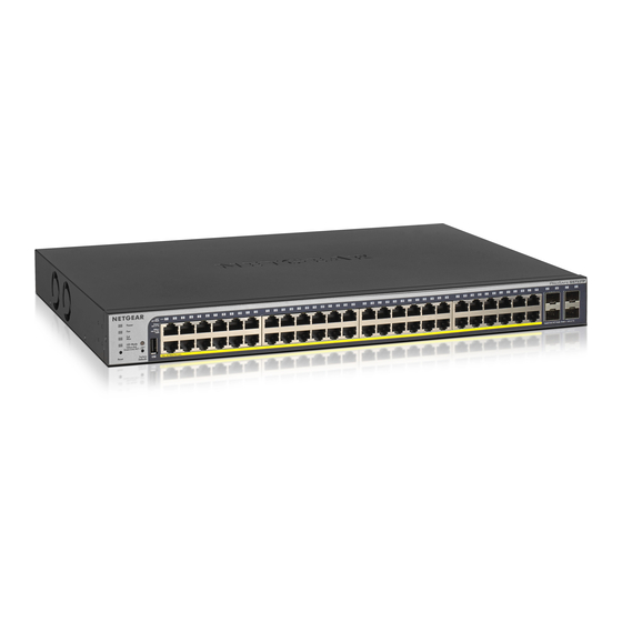
The switch provides twenty-four or forty-eight 10/100/1000BASE-T RJ-45 PoE+ ports and four SFP ports. The following figures show the front panels. (The front panels do not state the v2 model designation.) Figure 1. Front panel model GS728TPv2 (also applies to model GS728TPPv2) Models GS728TPv2 and GS728TPPv2 provide twenty-four 10/100/1000BASE-T RJ-45 PoE+ ports and four SFP ports. - Page 11 24-Port and 48-Port Gigabit PoE+ Smart Managed Pro Switches with 4 SFP Ports Table 1. Front panel Number Description Power LED For more information, see LEDs on page 12. Fan LED PoE Max LED LED Mode LEDs LED Mode button. This button lets you change the information that the port LEDs provide, which is either switching information (link, speed, and activity) or PoE information (PoE-powered and PoE fault).
-
Page 12: Leds
24-Port and 48-Port Gigabit PoE+ Smart Managed Pro Switches with 4 SFP Ports LEDs This section describes the LEDs on the front panel of the switch. Table 2. Front panel LEDs Description Power LED Solid green. The switch is powered on. Solid yellow. -
Page 13: Back Panel
The back panel provides a Kensington lock and AC power receptacle. (The switch integrates a fixed, internal power supply.) The console port is not for customer use. The following figures show the back panels. Figure 3. Back panel models GS728TPv2 and GS728TPPv2 Figure 4. Back panel models GS752TPv2 and GS752TPP Switch Hardware Interfaces The following sections describe the hardware interfaces on the switch. -
Page 14: Sfp Ports For Fiber Or Copper Connectivity
AGM732F SFP transceiver 1000BASE-LX, SFP long-reach multimode LC GBIC • AGM734 SFP transceiver 1000BASE-T, SFP copper RJ-45 GBIC For more information about NETGEAR SFP transceiver modules and cables, visit netgear.com/business/products/switches/modules-accessories. Reset Button The switch provides a Reset button on the front panel so that you can reboot the switch. Save the configuration before you press the Reset button. -
Page 15: Chapter 3 Applications
Applications The switch is designed to provide flexibility in configuring network connections. You can use the switch as an aggregation switch in a larger network or as a backbone switch in a small office or home office network to support 10 Mbps, 100 Mbps, and 1 Gbps Ethernet and fiber routers, switches, and hubs. -
Page 16: Poe Overview
Supplied power is prioritized according to the port order, up to the total power budget of the device. For example, for model GS728TPv2, port 1 receives the highest PoE priority, while port 24 is relegated to the lowest PoE priority. -
Page 17: Gigabit Aggregation Switching With Poe
PoE+ WiFi access points, and PoE VoIP phones. Figure 5. Sample aggregation switching with PoE+ Letter Device Letter Device Switch model GS728TPv2 Switch model GS108 (Gigabit unmanaged switch) Network router or firewall ReadyNAS Internet Computers and workstations... -
Page 18: Connect Poe Equipment In A Business Environment
24-Port and 48-Port Gigabit PoE+ Smart Managed Pro Switches with 4 SFP Ports Connect PoE Equipment in a Business Environment The following figure shows an example of how you can connect PoE+ wireless access points, PoE VoIP phones, and PoE surveillance equipment to the switch in a business environment. In a small office or home office network, you can connect the switch directly to your Internet router or Internet modem. -
Page 19: Connect Poe Equipment For Surveillance And Security
24-Port and 48-Port Gigabit PoE+ Smart Managed Pro Switches with 4 SFP Ports Connect PoE Equipment for Surveillance and Security The following figure shows an example of how you can connect PoE and non-PoE equipment to the switch for surveillance and security purposes. In a small office or home office network, you can connect the switch directly to your Internet router or Internet modem. -
Page 20: Chapter 4 Installation
Installation This chapter describes the installation procedures for the switch. Switch installation involves the steps described in the following sections: • Step 1: Prepare the Site • Step 2: Protect Against Electrostatic Discharge • Step 3: Unpack the Switch • Step 4: Install the Switch •... -
Page 21: Step 1: Prepare The Site
24-Port and 48-Port Gigabit PoE+ Smart Managed Pro Switches with 4 SFP Ports Step 1: Prepare the Site Before you install the switch, make sure that the operating environment meets the site requirements that are listed in the following table. Table 3. -
Page 22: Step 3: Unpack The Switch
24-Port and 48-Port Gigabit PoE+ Smart Managed Pro Switches with 4 SFP Ports • When unpacking a static-sensitive component from its shipping carton, leave it in the antistatic package until you are ready to install it. Just before unwrapping the antistatic package, discharge static electricity from your body. -
Page 23: Step 4: Install The Switch
Installation guide Resource CD with NETGEAR Smart Control Center utility If any item is missing or damaged, contact your local NETGEAR reseller for replacement. Step 4: Install the Switch You can install the switch in a standard 19-inch (48.26-centimeter) network equipment rack or on a flat surface. -
Page 24: Install The Switch On A Flat Surface
The following optional procedure describes how to install an optional SFP transceiver module into one of the SFP ports of the switch. Note Contact your NETGEAR sales office to purchase these modules. If you do not want to install an SFP module, skip this procedure. To install an SFP transceiver module: Insert the transceiver into the SFP port. -
Page 25: Step 6: Connect Devices To The Switch
24-Port and 48-Port Gigabit PoE+ Smart Managed Pro Switches with 4 SFP Ports Step 6: Connect Devices to the Switch The following procedure describes how to connect devices to the switch’s RJ-45 ports. The switch supports Auto Uplink technology, which allows you to attach devices using either straight-through or crossover cables. Use a Category 5 (Cat 5), Cat 5e, or Cat 6 cable that is terminated with an RJ-45 connector. -
Page 26: Step 9: Manage The Switch
Windows-based computer) for very basic setup. For more information about managing the switch, see the installation guide on the resource CD and the user manual, which you can download from downloadcenter.netgear.com. Note The switch’s default IP address is 192.168.0.239 and its default subnet mask is 255.255.255.0. -
Page 27: Chapter 5 Troubleshooting
Troubleshooting This chapter provides information about troubleshooting the switch. The chapter includes the following sections: • Troubleshooting Chart • PoE Troubleshooting Suggestions • Additional Troubleshooting Suggestions... -
Page 28: Troubleshooting Chart
24-Port and 48-Port Gigabit PoE+ Smart Managed Pro Switches with 4 SFP Ports Troubleshooting Chart The following table lists symptoms, possible causes, and possible solutions for problems that might occur. Table 4. Troubleshooting chart Symptom Possible Cause Possible Solution Power LED is off. Power is not supplied to the switch. -
Page 29: Poe Troubleshooting Suggestions
Switch integrity. If necessary, verify the integrity of the switch by resetting it. To reset the switch, disconnect the AC power from the switch and then reconnect the AC power. If the problem continues, contact NETGEAR technical support. For more information, visit the support website at netgear.com/support.
Need help?
Do you have a question about the GS728TPv2 and is the answer not in the manual?
Questions and answers