DSC PowerSeries PC1616 Installation Manual
System
enhancement
module
Hide thumbs
Also See for PowerSeries PC1616:
- Installation manual (73 pages) ,
- User manual (28 pages) ,
- Installation procedures (4 pages)

Related Manuals for DSC PowerSeries PC1616


Summary of Contents for DSC PowerSeries PC1616
-
Page 1: Installation Guide
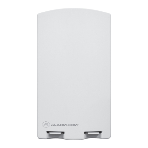
SYSTEM ENHANCEMENT MODULE DSC PowerSeries™ INSTALLATION GUIDE INSTALL WIZARD AVAILABLE AT ALARM.COM/SEMPOWERSERIES https://alarmadmin.alarm.com/web/wizard/v1/sem/powerseries?returnToUrl=%2Fhome.aspx&step=2... - Page 2 OVERVIEW The System Enhancement Module (SEM) can be used with DSC PowerSeries PC1616, PC1832, and PC1864 panels to enable wireless reporting of alarms and other system events using the CDMA, HSPA, or LTE wireless (cellular) network. The SEM is intended to be used as the primary communication path for all alarm signaling to the central monitoring station.
-
Page 3: Table Of Contents
TABLE OF CONTENTS Step 1: Verify Panel Compatibility ........4 Step 2: Create An Account ..........5 Step 3: Disconnect Power From Panel ......6 Step 4: Mount the SEM ............7 Step 5: Wire the SEM to the Panel ........8 Step 6: Power Up the Panel ..........9 Step 7: Broadcast Sensor Names ........9 Add &... -
Page 4: Step 1: Verify Panel Compatibility
STEP 1: VERIFY PANEL COMPATIBILITY The SEM is compatible with PowerSeries PC1616, PC1832, and PC1864 firmware version 4.2 or newer. -
Page 5: Step 2: Create An Account
STEP 2: CREATE AN ACCOUNT Before installing the SEM, first create a new Alarm.com customer account. We recommend creating the account at least 24 hours prior to installation. This will ensure that the SEM is activated prior to installation. To create an account, go to the Alarm.com Dealer Website or MobileTech and login. -
Page 6: Step 3: Disconnect Power From Panel
STEP 3: DISCONNECT POWER FROM PANEL Prior to disconnecting power from the panel, first verify that the panel is disarmed. Next, remove panel AC power and disconnect the backup battery. This is necessary to prevent damaging the panel or module while making wiring connections. -
Page 7: Step 4: Mount The Sem
STEP 4: MOUNT THE SEM You must be free of static electricity before handling electronic components. Touch a grounded metal surface before touching the circuit board. Press down on the bottom tabs of the enclosure cover to remove it and set it aside. Carefully remove the SEM circuit board by depressing the interior bottom tab. -
Page 8: Step 5: Wire The Sem To The Panel
STEP 5: WIRE THE SEM TO THE PANEL Verify panel AC power is removed and the backup battery is disconnected. 12V Battery +12V YELLOW (IN) GREEN (OUT) PowerSeries Panel • Connect panel terminal SEM GND to BLK. • Connect panel terminal YELLOW (IN) to YEL. -
Page 9: Step 6: Power Up The Panel
STEP 6: POWER UP THE PANEL Connect the backup battery and restore AC power to the panel. For the SEM to interact with the existing zones on the system, it must read them from the PowerSeries panel. The SEM will do a “zone scan” to read this information. -
Page 10: Add & Delete Z-Wave Devices
ADD & DELETE Z-WAVE DEVICES Please visit the Dealer Website Support Resources for a complete explanation of Z-Wave communication, Z-Wave signal strength, and additional installation resources. Alarm.com will not recognize any Z-Wave devices previously learned into the panel. These devices will need to be deleted from the previous Z-Wave network and added to the SEM for the customer to use Alarm.com’s home automation services (e.g. - Page 11 Using the Dealer Website Move all Z-Wave devices to their final location on the property. Navigate to the Equipment page on the Dealer Website. Click the emPower Devices tab. Open the Advanced Z-Wave Commands menu below the Equipment List. Click Add Z-Wave Devices. Wait for the bolded message: Checking for new devices on the network.
- Page 12 DELETING Z-WAVE DEVICES Using the Dealer Website or MobileTech is strongly recommended. Using MobileTech Open MobileTech and select the customer. Navigate to the Equipment List screen. Select emPower Management. Select Delete Z-Wave Devices. Wait for the bolded message: Checking for deleted devices on the network.
-
Page 13: Leds
LEDs The Alarm.com Module LEDs can be used to indicate communication errors, panel communication, network communication, and signal strength. System Enhancement Module (SEM) BOTTOM OF ALARM.COM MODULE FUNCTION Error LED: L1 will flash 1 to 8 times in a four-second interval to indicate specific error conditions such as a network error, panel communication error, or radio error. - Page 14 The Alarm.com module is registered on the cellular network but could not connect with Alarm.com. Contact Alarm.com Technical Support. The radio on the module is not working correctly. If this persists for more than a few minutes the module may need to be replaced.
- Page 15 LED L5 (YELLOW) L5 indicates Z-Wave errors. If you can’t add a device to the network, try deleting the device and re-adding it to the network. Contact Alarm.com Technical Support with additional issues. ALARM.COM MODULE STATES (MODES) There are three Alarm.com module states (modes). Idle Mode In Idle mode, the AC power is up, the battery level is greater than 11.5 volts, and the SEM is not currently connected to the Alarm.com servers.
-
Page 16: Frequently Asked Questions
FREQUENTLY ASKED QUESTIONS Will the customer be notified if the panel fails to communicate with Alarm.com? Yes, the SEM will automatically use the last available zone on the panel to display this information. The zone will be named “Communication Failure” and will be displayed on the keypad as if it were an open zone. How should I choose the best location to install the SEM? •... -
Page 17: Troubleshooting
Is the SEM compatible with DLS? The SEM cannot be used as a DLS communicator. DLS panel programming changes via another communication pathway (PC Link, POTS, etc.) will not be captured by the SEM until the system is power cycled. Do I need to change any programming settings for the SEM to work? No, there aren’t any required settings that need to be changed. -
Page 18: Specifications
SPECIFICATIONS Compatibility DSC PowerSeries PC1616, PC1832, and PC1864 version 4.2 or newer. Power 12 V nominal, 130 mA (continuous) 2000 mA Requirements (instantaneous peaks) maximum (from panel battery) Cellular Network Dual Band CDMA (3G), Dual Band HSPA (3G), or Dual Band 4G LTE... -
Page 19: Regulatory Information
REGULATORY INFORMATION Changes or modifications not expressly approved by Alarm.com can void the user’s authority to operate the equipment. This equipment has been tested and found to comply with the limits for a Class B digital device, pursuant to part 15 of the FCC Rules. These limits are designed to provide reasonable protection against harmful interference in a residential installation. - Page 20 NOTES SEM INSTALLATION GUIDE (PowerSeries) 2.0 | Copyright © 2017 Alarm.com. All rights reserved.
Need help?
Do you have a question about the PowerSeries PC1616 and is the answer not in the manual?
Questions and answers