SEH INU-100 Hardware Installation Manual
Usb deviceserver
Hide thumbs
Also See for INU-100:
- Quick installation manual (24 pages) ,
- Hardware installation manual (44 pages) ,
- Quick installation manual (28 pages)

Related Manuals for SEH INU-100


Summary of Contents for SEH INU-100
- Page 1 USB Deviceserver INU-100 Hardware Installation Guide MHAB-EB-INU100 Version: 1.1 | 2017-04...
- Page 2 Overview This 'Hardware Installation Guide' provides a description of the hardware installation of the INU-100. The initial setup is described in the 'Quick Installation Guide' . Table of contents 1. Do you need assistance? Contact us! Monday to Thursday 8:00 a.m. to 4:45 p.m. and Friday 8:00 a.m.
-
Page 3: Table Of Contents
Table of Contents Scope of Supply ........2 Technical Data. -
Page 4: Scope Of Supply
Guide description of the installation of the INU-100. (This document) Quick The Quick Installation Guide Installation provides a brief description of Guide the initial setup of the INU-100. microSD Inserted into microSD card card reader. [en] Hardware Installation Guide... -
Page 5: Technical Data
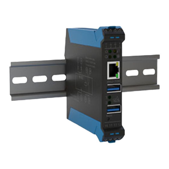
Technical Data Device Overview power connectors activity LED power LED status LED network connector relay LED USB ports USB port LEDs relay reset button connectors micro SD card reader snap lock Hardware Installation Guide [en]... -
Page 6: Dimensions & Weight
Properties Values Network connection logical: IEEE 802.3 (1000BaseT, 100BaseTX and 10BaseT) physical: 1 × RJ-45 Device connection - 2 × USB 3.0 SuperSpeed - 1 × microSD card reader Operating - ambient temperature: 5–40 °C Environment - relative humidity: 20–80 % Dimensions &... -
Page 7: Connectors
Connectors normally normally closed open power supply 1 power supply 2 (You can find this circuit diagram on the INU server's side.) Power supply The INU server can be fed by 2 power supplies. While one power supply is actively supplying, the other serves as backup. - Page 8 Relay You can use the INU server's relay for various purposes in your environment. For more information see the INU User Manual; available at: http://www.seh-technology.com/services/ downloads/industrial/inu-100.html Type potential-free changeover switch Contact data: switching voltage: max. 60 V DC or 42 V AC switching current: max.
-
Page 9: Type Plate
Cable IEC: 400 V / 0.2–2.5mm² 300 V / 10 A / AWG 26–AWG 12 Required stripping: approx. 7 mm Insertion: stripped end with or without end terminals Fuse none Type Plate The type plate gives important product information, such as hardware and certification information as well as the serial number. -
Page 10: Led Display
LED Display The LEDs of the INU server provide information about its status. Action Color Description Power permanently – INU server is on. permanently green INU server is off. Activity blinks at yellow Indicates the exchange irregular of network data packets. intervals Status permanently... - Page 11 Action Color Description permanently – No USB device is ports connected to the 1–2 respective port. permanently green A USB device is connected to the respective port. permanently orange The connection to the respective port and the attached USB device is activated.
-
Page 12: Safety Regulations
Safety Regulations INU servers are network devices for use in industrial environments. The INU-100 is designed for the integration of USB devices into TCP/IP networks. Important: Before starting the installation and the initial setup procedure as well during the operation of the INU server, please note the following safety regulations. - Page 13 be installed in the same control cabinet. • The low-voltage cable between the power supply and the device must not be longer than 3 m. • The maximum load for the relay contacts is 60 V for DC / 42 V for AC and a current of max. 3 A. •...
-
Page 14: Hardware Installation
Hardware Installation Install the INU-100 on a top-hat rail (DIN rail according to DIN EN 60715, 35 mm wide). You can directly connect up to two USB devices to the INU-100. In addition, you can connect a load to the relay. - Page 15 2. Connect the power supply/supplies (5) of your server rack to the INU-100: 3. (Optional) Connect an electrical load to the INU server's relay (6): Hardware Installation Guide [en]...
- Page 16 4. Connect the network cable (RJ-45) to the INU server. 5. Connect the USB devices to the USB ports of the INU server: [en] Hardware Installation Guide...
-
Page 17: After The Hardware Installation
Important: Upon delivery, the microSD card is already inserted into the microSD card reader and ready for use (installation or formatting are not required). Hardware Installation Guide [en]... - Page 18 After the Hardware Installation As soon as the hardware has been installed, the INU server can be set up for operation. All information on how to do this you will find in the enclosed document 'Quick Installation Guide' . [en] Hardware Installation Guide...
-
Page 19: Regulatory Compliance Information
Regulatory Compliance Information EC – Declaration of Conformity Manufacturer's name and address: SEH Computertechnik GmbH Suedring 11, 33647 Bielefeld, Germany Phone: +49 (0)521 94226-0 Herewith SEH Computertechnik GmbH declares that Product: USB Deviceserver Type designation: INU-100 Serial no.: 287 yyyy mm nnnnn (yyyy = year, mm = month, nnnnn = seq. - Page 20 Bielefeld, March 3, 2017 Dipl.-Ing. Rainer Ellerbrake, General Manager Important: The latest version of the EC declaration of conformity can be downloaded from the homepage of SEH Computertechnik GmbH: http://www.seh-technology.com/ services/ce-notifications.html [en] Hardware Installation Guide...
-
Page 21: Federal Communication Commission (Fcc) Notice
The user has to comply with all instructions defined in this manual. It is not allowed to do product modifications not expressly approved by SEH. NOTE: This equipment has been tested and found to comply with the limits for a Class B digital device, pursuant to part 15 of the FCC Rules. - Page 22 Inhaltsverzeichnis Lieferumfang ........21 Technische Daten .
-
Page 23: Lieferumfang
Lieferumfang Bitte überprüfen Sie den Packungsinhalt auf Vollständigkeit, bevor Sie die Installation beginnen: INU-Server USB Deviceserver 'INU-100' Hardware Hardware Installation Installation Guide beinhaltet eine kurze Guide Beschreibung der Installation des INU-100. (Dieses Dokument) Quick Der Quick Installation Guide Installation... -
Page 24: Technische Daten
Technische Daten Geräte-Übersicht Stromanschlüsse Activity LED Power-LED Status-LED Netzwerk Relais-LED anschluss USB-Ports USB-Port-LEDs Relais- kontakte Reset-Taster mircoSD- Card- Schnapp- Reader verbinder [de] Hardware Installation Guide... -
Page 25: Abmessungen & Gewicht
Eigenschaften Werte Netzwerkanschluss Logisch: IEEE 802.3 (1000BaseT, 100BaseTX und 10BaseT) Physisch: 1 × RJ-45 Geräteanschluss - 2 × USB 3.0 SuperSpeed - 1 × microSD-Card-Reader Betriebsumgebung - Umgebungstemperatur: 5–40 °C - Relative Luftfeuchtigkeit: 20–80 % Abmessungen & Gewicht 114 mm 22,5 mm 150 g Hardware Installation Guide... -
Page 26: Anschlüsse
Anschlüsse Öffner Schließer Strom- versorgung 1 Stromversorgung 2 (Den Schaltplan finden Sie auch auf der Seite des INU-Servers.) Stromversorgung Der INU-Server kann über 2 Stromquellen versorgt werden. Eine Stromquelle übernimmt die Versorgung, die andere dient als Backup. WARNUNG Das Gerät und das oder die Versorgungsnetzteile müssen im selben Schaltschrank installiert sein. - Page 27 - ca. 550 mA bei Volllast auf den USB-Ports Relais Das Relais des INU-Servers kann für verschiedenste Zwecke in Ihrer Umgebung genutzt werden. Weitere Informationen finden Sie im INU-Benutzerdokumentation; verfügbar unter: http://www.seh.de/services/downloads/ industrial/inu-100.html potentialfreier Umschalter Kontaktdaten Schaltspannung: maximal 60 V Gleichspannung oder 42 V Wechselspannung Schaltstrom:...
-
Page 28: Typenschild
Kabel IEC: 400 V / 0,2–2,5mm² 300 V / 10 A / AWG 26–AWG 12 erforderliche Abisolierung: ca. 7 mm Einführung: Litze mit oder ohne Ader- Endhülse Sicherung keine Typenschild Auf dem Typenschild finden Sie wichtige Angaben zu Ihrem Produkt, wie z.B. Informationen zur Hardware und zu Zertifizierungen sowie die Seriennummer. -
Page 29: Led-Anzeige
LED-Anzeige Durch die Interpretation des LED-Leuchtverhaltens kann der Zustand des INU-Servers ermittelt werden. Aktion Farbe Beschreibung Power Dauer- – INU-Server ist eingeschaltet. Dauer-An grün INU-Server ist ausgeschaltet. Activity unregel- gelb Signalisiert den Austausch mäßiges von Netzwerk- Blinken Datenpaketen. Status Dauer- –... - Page 30 Aktion Farbe Beschreibung USB-Port Dauer- – Es ist kein USB-Gerät am 1–2 betreffenden Port angeschlossen. Dauer-An grün Es ist ein USB-Gerät am betreffenden Port angeschlossen. Dauer-An orange Die Verbindung zum betreffenden Port und dem daran angeschlossenen USB- Gerät ist aktiviert. Relais Dauer- –...
-
Page 31: Sicherheitsvorschriften
Sicherheitsvorschriften INU-Server sind Netzwerkgeräte für den Gebrauch in Industrieumgebungen. Der INU-100 dient dem Einbinden von USB-Geräten in TCP/IP-Netzwerken. Wichtig: Beachten Sie vor der Installation und Inbetriebnahme sowie beim Betrieb des INU- Servers die folgenden Sicherheitsvorschriften, um sich und andere vor Personenschäden zu schützen sowie Beschädigungen am Gerät zu... - Page 32 (< 3 m), das unter www.usb.org gelistet ist. • Das Gerät und das oder die Versorgungsnetzteile müssen im selben Schaltschrank installiert sein. • Das Niederspannungskabel zwischen dem Netzteil und dem Gerät darf maximal 3 m lang sein. • Die Relaiskontakte dürfen mit maximal 60 V Gleichspan- nung / 42 V Wechselspannung und einem Strom von ma- ximal 3 A belastet werden.
-
Page 33: Hardware-Installation
Hardware-Installation Der INU-100 wird auf eine Hutschiene (Tragschiene gemäß DIN EN 60715, 35 mm breit) installiert. Bis zu zwei USB-Geräte können direkt am INU-100 angeschlossen werden. Zudem lässt sich ein Verbraucher am Relais anschließen. Netzwerk Strom 1 Strom 2... - Page 34 2. Schließen Sie die Stromversorgung(en) (24) Ihres Ser- verschranks an den INU-100 an: 3. (Optional) Schließen Sie einen Verbraucher an das Relais (25) des INU-Servers an: [de] Hardware Installation Guide...
- Page 35 4. Verbinden Sie das Netzwerkkabel (RJ-45) mit dem INU- Server: 5. Schließen Sie die USB-Geräte an die USB-Ports des INU- Servers an: Wichtig: Die microSD-Karte befindet sich bei Auslieferung bereits im microSD-Card-Reader und ist betriebsbereit (kein Anschließen oder Formatieren erforderlich). Hardware Installation Guide [de]...
-
Page 36: Nach Der Hardware-Installation
Nach der Hardware-Installation Sobald die Hardware-Installation durchgeführt ist, kann der INU-Server in Betrieb genommen werden. Alle Informationen dazu finden Sie im beigelegten Dokument 'Quick Installation Guide' . [de] Hardware Installation Guide... -
Page 37: Konformitäts-Erklärungen
Konformitäts-Erklärungen CE-Konformitätserklärung Herstellername und -adresse: SEH Computertechnik GmbH Südring 11, 33647 Bielefeld, Deutschland Tel.: +49 (0)521 94226-0 Hiermit erklärt SEH Computertechnik GmbH, dass Produkt: USB Deviceserver Typenbezeichnung: INU-100 Seriennummer: 287 yyyy mm nnnnn (yyyy = Jahr, mm = Monat, nnnnn = fortlaufende Nummer) den folgenden Bestimmungen entspricht RICHTLINIE 2014/30/EU DES EUROPÄISCHEN PARLAMENTS... - Page 38 Bielefeld, 3. März 2017 Dipl.-Ing. Rainer Ellerbrake, Geschäftsführer Wichtig: Die aktuelle CE-Konformitätserklärung kann von der SEH Computertechnik GmbH-Webseite geladen werden: http://www.seh.de/services/ce-erklaerungen.html [de] Hardware Installation Guide...
-
Page 39: Federal Communication Commission (Fcc) Notice
The user has to comply with all instructions defined in this manual. It is not allowed to do product modifications not expressly approved by SEH. NOTE: This equipment has been tested and found to comply with the limits for a Class B digital device, pursuant to part 15 of the FCC Rules. - Page 40 Sales Contacts and Information: http://www.seh-technology.com/sales Downloads: http://www.seh-technology.com/services/downloads.html © 2017 SEH Computertechnik GmbH All trademarks, registered trademarks, logos and product names are property of their respective owners. The contents of this document are subject to change without notification. This product uses 'Open Source Software' . For further information, please contact http://www.seh.de.
Need help?
Do you have a question about the INU-100 and is the answer not in the manual?
Questions and answers