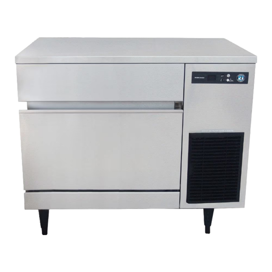
Hoshizaki IM-200BAA Service Manual
Self-contained cuber
Hide thumbs
Also See for IM-200BAA:
- Instruction manual (24 pages) ,
- Instruction manual (24 pages) ,
- Service manual (39 pages)
Table of Contents
Advertisement
Quick Links
Advertisement
Table of Contents

Related Manuals for Hoshizaki IM-200BAA


Summary of Contents for Hoshizaki IM-200BAA
- Page 1 SERVICE MANUAL Number: M063-972 Issued: 10-31-2015...
- Page 2 IMPORTANT...
- Page 3 IMPORTANT CONTENTS...
-
Page 4: Important Safety Information
Important Safety Information WARNING Indicates a hazardous situation which could result in death or serious injury. NOTICE Indicates a situation which could result in damage to the appliance or property. IMPORTANT Indicates important information about the installation, use, and care of the appliance. WARNING precautions including the following: •... - Page 5 WARNING, continued NOTICE...
- Page 6 I. Construction and Water/Refrigeration Circuit Diagram A. Construction 1. Air-Cooled Model (BAA)
- Page 8 B. Water/Refrigeration Circuit Diagram 1. Air-Cooled Model (BAA)
- Page 9 II. Sequence of Operation and Service Diagnosis A. Sequence of Operation Flow Chart "IM" Control Board 1. 30-Sec. 3. Freeze Cycle 2. Harvest Cycle Cycle Startup Steps Cycle Startup Water Tank Closed (Actuator Motor PS) Comp Comp Comp Shutdown and Restart Sequence Flow Chart 1.
-
Page 10: Sequence Of Operation
B. Sequence of Operation 1. Startup Cycle 2. Harvest Cycle Initial Harvest Initial Harvest after Bin Control Normal Harvest after Power On Initiated Restart Note Setting All WT WT>48°F (9°C) WT>48°F (9°C) 3. Freeze Cycle Initial Freeze Initial Freeze after Bin Control Normal Freeze after Power On Initiated Restart... - Page 11 temp. (absolute value) × time (min.) = (absolute value of CB Setting 2) × (CB Setting 3) temp. (absolute value) × time (min.) = 264 4. Shutdown Comp WT–...
-
Page 12: Service Diagnosis Table
C. Service Diagnosis Table No Ice Production - Possible Cause... - Page 13 Low Ice Production - Possible Cause Long Harvest Cycle Long Freeze Cycle Slab Does Not Break Into Separate Cubes - Possible Cause Cubes Drop Separately - Possible Cause Imperfect Ice Production - Possible Cause Large-Hole Cubes - Possible Cause (Also see III.H.1. Dimple Diameter")
- Page 14 Large-Hole Cubes - Possible Cause (Also see III.H.1. Dimple Diameter") Cloudy Cubes - Possible Cause...
- Page 15 D. Bin Control Check and Cleaning 1. Bin Control Check Fig. 1...
-
Page 16: Choking Hazard
2. Bin Control Cleaning WARNING CHOKING HAZARD:... - Page 17 E. Evaporator Thermistor Check Comp...
- Page 18 III. Controls and Adjustments A. Control Switch B. Control Board NOTICE...
-
Page 19: Control Board Layout
1. Control Board Layout • CN16 Connector • CN11 Connector • CN13 Connector • CN10 Connector • CN9 Connector • CN4 Connector • RESET Button • CN1 Connector • SERVICE 1 Button • SERVICE 2 Button • CN2 Connector • CN5 Connector •... - Page 20 C. Control Buttons 1. RESET Button 2. SERVICE 1 and SERVICE 2 Buttons NOTICE! Do not decrease dimple size below 3/16" (5 mm). Fig. 2...
-
Page 21: Control Board Settings
D. Control Board Settings NOTICE Control Board (CB) Setting Menu IM-200BAA Category No. Item Range Default DO NOT ADJUST DO NOT ADJUST... - Page 22 Control Board (CB) Setting Menu IM-200BAA Category No. Item Range Default...
- Page 23 Control Board (CB) Setting Menu IM-200BAA Category No. Item Range Default DO NOT ADJUST DO NOT ADJUST DO NOT ADJUST DO NOT ADJUST DO NOT ADJUST DO NOT ADJUST...
- Page 24 Control Board (CB) Setting Menu IM-200BAA Category No. Item Range Default...
-
Page 25: Control Board Information Display
E. Control Board Information Display Control Board Information Display History Cleared by Pressing and Holding SERVICE 1 and SERVICE 2 Buttons Simultaneously for 5 Sec. when Item Value No. Item Description is Displayed? -
Page 26: Control Board Model Code Setting
Control Board Information Display History Cleared by Pressing and Holding SERVICE 1 and SERVICE 2 Buttons Simultaneously for 5 Sec. when Item Value No. Item Description is Displayed? F. Control Board Model Code Setting 1. Control Board Replacement WARNING... - Page 27 2. Checking or Changing the Control Board Model Code G. Error Codes...
- Page 28 Error Codes Error Problem Corrective Action/Reset Details Code...
-
Page 29: Quick Adjustments
Error Codes Error Problem Corrective Action/Reset Details Code H. Quick Adjustments 1. Dimple Diameter NOTICE! Do not decrease the dimple diameter below 3/16" (5 mm). a) To increase dimple diameter: b) To decrease dimple diameter: NOTICE! Do not decrease dimple size below 3/16"... - Page 30 Normal Position Drain Position Fig. 3...
- Page 31 IV. Refrigeration Circuit and Component Service Information WARNING • • • CHOKING HAZARD: • A. Refrigeration Circuit Service Information WARNING NOTICE 1. Refrigerant Recovery...
- Page 32 2. Brazing WARNING NOTICE 3. Evacuation and Recharge (R-134a) IMPORTANT...
- Page 33 B. Component Service Information NOTICE Component Notes...
-
Page 34: Maintenance
V. Maintenance WARNING • • • • CHOKING HAZARD: Maintenance Schedule Frequency Area Task... - Page 35 VI. Preparing the Appliance for Periods of Non-Use NOTICE 1. Remove the water from the icemaker water supply line: Fig. 4...
- Page 36 2. Drain the water tank: VII. Disposal IMPORTANT...
-
Page 37: Technical Information
VIII. Technical Information 1. IM-200BAA AC SUPPLY VOLTAGE 115/60/1 AMPERAGE 7.6 A ( 5 Min. Freeze AT 104°F / WT 80°F) MINIMUM CIRCUIT AMPACITY 15 A MAXIMUM FUSE SIZE 15 A APPROXIMATE ICE PRODUCTION Ambient WATER TEMP. (°F) PER 24 HR. -
Page 38: Performance Data
B. Performance Data 1. IM-200BAA APPROXIMATE ICE WATER TEMP. (ºF/ºC) AMBIENT TEMP. PRODUCTION PER 24 HR. (ºF/ºC) 50/10 70/21 90/32 70/21 80/27 90/32 lbs./day kg./day 100/38 APPROXIMATE ELECTRIC 70/21 CONSUMPTION 80/27 90/32 watts 100/38 APPROXIMATE WATER 70/21 0.18 0.16 0.15 CONSUMPTION PER 24 HR. - Page 39 C. Wiring Diagram 1. IM-200BAA...
Need help?
Do you have a question about the IM-200BAA and is the answer not in the manual?
Questions and answers