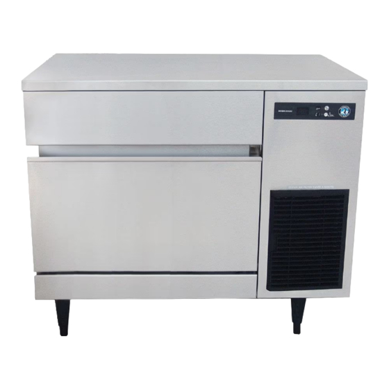
Hoshizaki IM-200BAA Service Manual
Self-contained cuber
Hide thumbs
Also See for IM-200BAA:
- Instruction manual (24 pages) ,
- Service manual (40 pages) ,
- Instruction manual (24 pages)

Related Manuals for Hoshizaki IM-200BAA


Summary of Contents for Hoshizaki IM-200BAA
- Page 1 All manuals and user guides at all-guides.com SERVICE MANUAL Number: M063-972 Issued: 10-31-2015...
- Page 2 All manuals and user guides at all-guides.com IMPORTANT...
- Page 3 All manuals and user guides at all-guides.com IMPORTANT CONTENTS...
-
Page 4: Important Safety Information
All manuals and user guides at all-guides.com Important Safety Information WARNING Indicates a hazardous situation which could result in death or serious injury. NOTICE Indicates a situation which could result in damage to the appliance or property. IMPORTANT Indicates important information about the installation, use, and care of the appliance. - Page 5 All manuals and user guides at all-guides.com WARNING, continued NOTICE...
- Page 6 All manuals and user guides at all-guides.com I. Construction and Water/Refrigeration Circuit Diagram A. Construction 1. Air-Cooled Model (BAA)
- Page 7 All manuals and user guides at all-guides.com...
- Page 8 All manuals and user guides at all-guides.com B. Water/Refrigeration Circuit Diagram 1. Air-Cooled Model (BAA)
- Page 9 All manuals and user guides at all-guides.com II. Sequence of Operation and Service Diagnosis A. Sequence of Operation Flow Chart "IM" Control Board 1. 30-Sec. 3. Freeze Cycle 2. Harvest Cycle Cycle Startup Steps Cycle Startup Water Tank Closed (Actuator Motor PS) Comp Comp Comp...
-
Page 10: Sequence Of Operation
All manuals and user guides at all-guides.com B. Sequence of Operation 1. Startup Cycle 2. Harvest Cycle Initial Harvest Initial Harvest after Bin Control Normal Harvest Note after Power On Initiated Restart Setting All WT WT>48°F (9°C) WT>48°F (9°C) 3. Freeze Cycle Initial Freeze Initial Freeze after Bin Control Normal Freeze... - Page 11 All manuals and user guides at all-guides.com temp. (absolute value) × time (min.) = (absolute value of CB Setting 2) × (CB Setting 3) temp. (absolute value) × time (min.) = 264 4. Shutdown Comp WT–...
-
Page 12: Service Diagnosis Table
All manuals and user guides at all-guides.com C. Service Diagnosis Table No Ice Production - Possible Cause... - Page 13 All manuals and user guides at all-guides.com Low Ice Production - Possible Cause Long Harvest Cycle Long Freeze Cycle Slab Does Not Break Into Separate Cubes - Possible Cause Cubes Drop Separately - Possible Cause Imperfect Ice Production - Possible Cause Large-Hole Cubes - Possible Cause (Also see III.H.1.
- Page 14 All manuals and user guides at all-guides.com Large-Hole Cubes - Possible Cause (Also see III.H.1. Dimple Diameter") Cloudy Cubes - Possible Cause...
- Page 15 All manuals and user guides at all-guides.com D. Bin Control Check and Cleaning 1. Bin Control Check Fig. 1...
-
Page 16: Choking Hazard
All manuals and user guides at all-guides.com 2. Bin Control Cleaning WARNING CHOKING HAZARD:... - Page 17 All manuals and user guides at all-guides.com E. Evaporator Thermistor Check Comp...
- Page 18 All manuals and user guides at all-guides.com III. Controls and Adjustments A. Control Switch B. Control Board NOTICE...
- Page 19 All manuals and user guides at all-guides.com 1. Control Board Layout • CN16 Connector • CN11 Connector • CN13 Connector • CN10 Connector • CN9 Connector • CN4 Connector • RESET Button • CN1 Connector • SERVICE 1 Button • SERVICE 2 Button •...
- Page 20 All manuals and user guides at all-guides.com C. Control Buttons 1. RESET Button 2. SERVICE 1 and SERVICE 2 Buttons NOTICE! Do not decrease dimple size below 3/16" (5 mm). Fig. 2...
-
Page 21: Control Board Settings
All manuals and user guides at all-guides.com D. Control Board Settings NOTICE Control Board (CB) Setting Menu IM-200BAA Category No. Item Range Default DO NOT ADJUST DO NOT ADJUST... - Page 22 All manuals and user guides at all-guides.com Control Board (CB) Setting Menu IM-200BAA Category No. Item Range Default...
- Page 23 All manuals and user guides at all-guides.com Control Board (CB) Setting Menu IM-200BAA Category No. Item Range Default DO NOT ADJUST DO NOT ADJUST DO NOT ADJUST DO NOT ADJUST DO NOT ADJUST DO NOT ADJUST...
- Page 24 All manuals and user guides at all-guides.com Control Board (CB) Setting Menu IM-200BAA Category No. Item Range Default...
-
Page 25: Control Board Information Display
All manuals and user guides at all-guides.com E. Control Board Information Display Control Board Information Display History Cleared by Pressing and Holding SERVICE 1 and SERVICE 2 Buttons Simultaneously for 5 Sec. when Item Value No. Item Description is Displayed? -
Page 26: Control Board Model Code Setting
All manuals and user guides at all-guides.com Control Board Information Display History Cleared by Pressing and Holding SERVICE 1 and SERVICE 2 Buttons Simultaneously for 5 Sec. when Item Value No. Item Description is Displayed? F. Control Board Model Code Setting 1. - Page 27 All manuals and user guides at all-guides.com 2. Checking or Changing the Control Board Model Code G. Error Codes...
- Page 28 All manuals and user guides at all-guides.com Error Codes Error Problem Corrective Action/Reset Details Code...
-
Page 29: Quick Adjustments
All manuals and user guides at all-guides.com Error Codes Error Problem Corrective Action/Reset Details Code H. Quick Adjustments 1. Dimple Diameter NOTICE! Do not decrease the dimple diameter below 3/16" (5 mm). a) To increase dimple diameter: b) To decrease dimple diameter: NOTICE! Do not decrease dimple size below 3/16"... - Page 30 All manuals and user guides at all-guides.com Normal Position Drain Position Fig. 3...
- Page 31 All manuals and user guides at all-guides.com IV. Refrigeration Circuit and Component Service Information WARNING • • • CHOKING HAZARD: • A. Refrigeration Circuit Service Information WARNING NOTICE 1. Refrigerant Recovery...
- Page 32 All manuals and user guides at all-guides.com 2. Brazing WARNING NOTICE 3. Evacuation and Recharge (R-134a) IMPORTANT...
- Page 33 All manuals and user guides at all-guides.com B. Component Service Information NOTICE Component Notes...
-
Page 34: Maintenance
All manuals and user guides at all-guides.com V. Maintenance WARNING • • • • CHOKING HAZARD: Maintenance Schedule Frequency Area Task... - Page 35 All manuals and user guides at all-guides.com VI. Preparing the Appliance for Periods of Non-Use NOTICE 1. Remove the water from the icemaker water supply line: Fig. 4...
- Page 36 All manuals and user guides at all-guides.com 2. Drain the water tank: VII. Disposal IMPORTANT...
-
Page 37: Technical Information
All manuals and user guides at all-guides.com VIII. Technical Information 1. IM-200BAA AC SUPPLY VOLTAGE 115/60/1 AMPERAGE 7.6 A ( 5 Min. Freeze AT 104°F / WT 80°F) MINIMUM CIRCUIT AMPACITY 15 A MAXIMUM FUSE SIZE 15 A APPROXIMATE ICE PRODUCTION Ambient WATER TEMP. -
Page 38: Performance Data
All manuals and user guides at all-guides.com B. Performance Data 1. IM-200BAA APPROXIMATE ICE WATER TEMP. (ºF/ºC) AMBIENT TEMP. PRODUCTION PER 24 HR. (ºF/ºC) 50/10 70/21 90/32 70/21 80/27 90/32 lbs./day kg./day 100/38 APPROXIMATE ELECTRIC 70/21 CONSUMPTION 80/27 90/32 watts... - Page 39 All manuals and user guides at all-guides.com C. Wiring Diagram 1. IM-200BAA...
Need help?
Do you have a question about the IM-200BAA and is the answer not in the manual?
Questions and answers