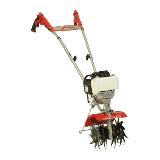
Mantis 7940 Quick Start Manual
4-cycle plus (gas only)
Hide thumbs
Also See for 7940:
- Operator's & parts manual (40 pages) ,
- Quick assembly sheet (2 pages) ,
- Operator and parts manual (40 pages)
Advertisement
Quick Links
TIP: UNPACK CAREFULLY AND KEEP ENGINE IN IT'S CARDBOARD CRADLE.
IT WILL MAKE IT EASIER TO ASSEMBLE!
A.
Open the top of the box and remove the tine box from the top of the box.
B.
Lay the box on one side and open the bottom fl aps.
C.
Return the box to an upright position and pull the
box straight up and over the enclosed tiller. The en-
gine and throttle handle will be sitting upright in the
cradle to assist in assembly, as shown. Locate the
A
B
C
hardware bag. (It may be in the cardboard cradle)
NOTE: Keep cardboard cradle on for assembly.
Key
Qty.
Part No. Description
WHAT'S IN THE BOX?
T7
2
T9
1
T11
2
T12
2
T13
2
T14
4
T15
2
T41
2
T42
2
T49
1
T50
1
TOOLS NEEDED TO ASSEMBLE THE TILLER:
• Two (2) 7/16" wrenches
• One (1) 3/8" wrench for kickstand assembly
W 45
W <
W 7<
W 83
W 75
W 44
W 48
W 47
W 74
W 46
W :
STEP 1:
ATTACH LOWER HANDLES
A
B
A.
Fit a handle clamp (T7) along the outside of the short leg of one handle, lining up the holes on
the clamp and the leg
B.
Take one of the two 3-inch bolts (T11) and slide it through the fi rst set of holes – near the
elbow where the lower handle curves. Then slide the other clamp onto the other
handles short leg. Add a lock nut (T14) and tighten by hand.
C.
Locate the recessed channels below the engine, and slide the handles you've just put together
into them as shown.
D.
Insert them from the rear so that they come from behind the Mantis logo as shown
(or you'll be tilling backwards!).
E.
Slide the second 3-inch bolt through the second set of
holes in the short legs, add a lock nut and tighten fi nger tight.
Handle Clamps
NEED HELP?
Throttle Clip
Bolts (3" long)
Call 800-366-6268 or go to www.mantis.com
Knobs
Acorn Nuts
Lock Nuts
Cap Screws
Tine Retaining Pins
Carriage Bolts
Kickstand
Kickstand Bracket and Screws
STEP 3:
INSTALL TINES
A
B
A. NOW
remove your tiller from the cardboard cradle
and lay it on its side. Open tine box. Remove tines
and retaining pins (T41). Pins are in the hardware bag.
Note: one side of the tine has an O shaped hole while the
other has a D shaped hole.
B.
Attach tine so that O hole slides onto axle fi rst. When axle
protrudes from top side, it will line up with D shaped hole.
C.
Slide retaining pin through hole in axle to secure tine. Repeat on the other side.
STEP 2:
ATTACH UPPER HANDLES
C
D
A.
Lightly squeeze lower handle towards
Lightly squeeze lower handle towards
one another so that they line up with
two smaller holes on carrying handle –
then slide carrying handle over and down
lower handle. It will rest 4-6" above
fender.
B.
Take upper handle with trigger and line
it up with the lower handle. Insert the
carriage bolt (T42) from the outside in.
Hardware
Top
Bracket
¼-20 x 0.5"
Flange
Screw
FOR TILLING,
attach the tines so the points
T49
of the blades face forward —
away from the operator. The
tines' points will contact the
C
A.
Lean the Tiller Handles against a sturdy surface, so the tiller is supported in the upright
ground fi rst.
position. Place the Top Bracket over the Lower Handles and below the Carry Handle.
T50- Kickstand bracket
B.
Place the Bottom Bracket of the Kickstand Stand Assembly (T49) under the Lower Handles
and hardware bag
FOR CULTIVATING,
T49- Kickstand
and line up the holes in both brackets.
Stand Assembly
reverse the tines so that
C.
Insert two screws through the holes in the Top Bracket and into the threaded inserts of the
the points of the tines face
Lower Bracket. Tighten with the 3/8" wrench.
backward — toward the
operator. Now the long fl at
KICKSTAND POSITION: Place kickstand in the folded (up) position. Kickstand should be
part of the tine's blade will
centered between Lower Handles. If not, loosen screws slightly, adjust as necessary and
contact the ground fi rst.
re-tighten the screws.
Do not operate the engine in a confi ned
space where dangerous carbon monoxide
fumes can collect.
4 CYCLE TILLER FUELING AND OIL
• Rock the tiller forward so that it rests on the
A
B
D
E
fuel tank. It is important to position the Mantis
Screw on knob and tighten (T12).
Cap the exposed bolt with an acorn nut
(T13) and hand tighten until snug. Do not
over tighten.
C.
Repeat step B to install other handle.
Fueling your Mantis 4-Cycle Tiller/Cultivator is easy. Unscrew the gas cap and fi ll the tank about
D.
Use the clip(T9) to secure the black
four-fi fths of the way up with 89 octane unleaded gasoline. And remember, always drain the gas when
cable and wire in place on the lower
transporting the unit from one location to another.
handle.
E.
Install the handle brace. Line it up with
the holes on the upper handles. Then
insert a cap screw (T15) and lock nut
ALTERNATIVE FUELS, SUCH AS E-15 (20% ETHANOL), E-85 (85% ETHANOL) OR ANY FUELS NOT MEETING HONDA REQUIREMENTS ARE NOT APPROVED FOR USE IN
GASOLINE ENGINES. USE OF ALTERNATIVE FUELS MAY CAUSE PERFORMANCE PROBLEMS, LOSS OF POWER, OVERHEATING, FUEL VAPOR LOCK AND UNINTENDED
(T14) on either side. Use a wrench to
MACHINE OPERATION, INCLUDING, BUT NOT LIMITED TO, IMPROPER CLUTCH ENGAGEMENT. ALTERNATIVE FUELS MAY ALSO CAUSE PREMATURE DETERIORATION
tighten cap screws and lock nuts, and
OF FUEL LINES, GASKETS, CARBURETORS AND OTHER ENGINE COMPONENTS.
then tighten all nuts and bolts throughout
the assembly fi rmly and securely.
IT IS NORMAL FOR YOUR 4 STROKE ENGINE TO SMOKE FOR THE FIRST MINUTE OR TWO OF OPERATION, HOWEVER IT IS NOT NECESSARY
FOR THIS TO OCCUR EVERY TIME. THIS IS A RESULT OF THE OIL BEING PULLED THROUGH THE ENGINE FOR
QUICK ASSEMBLY SHEET
4 CYCLE TILLER STARTING
Tools Needed: 3/8" wrench.
Kickstand Assembly for Models 7924, 7925, 7940
STEP 4:
ATTACH KICKSTAND
Top Bracket
Bottom Bracket
Tighten Hardware
T50
• First, make sure the start/stop switch, located on
the throttle handle, is in the start position, which
is indicated by the "I" symbol.
Step 8
• Close the choke by moving the choke lever to
Step 10
Lean the Tiller Handles against a sturdy
Step 9
the up position.
surface, so the tiller is supported in the
Insert two screws through the
Place the Bottom Bracket of
• Press the primer bulb approximately 6 times
upright position. Place the Top Bracket
holes in the Top Bracket and into
the Kickstand Stand
over the Lower Handles and below the
Assembly T49 under the
the threaded inserts of the Lower
until he bulb is fi lled with gas. Once it is fi lled,
Carry Handle.
Bracket. Tighten with the 3/8"
Lower Handles and line up
press it two more times.
wrench.
the holes in both brackets.
• Pull the starter cord lightly until you feel
Kickstand Position
resistance and then give it a short, brisk pull. Your
Place the Kickstand in the
tiller should start immediately. Do not pull the
folded position. The
cord all the way out and do not let it snap back
Kickstand should be centered
into the starter housing.
between the Lower Handles.
If not, loosen the screws
slightly, adjust as necessary
and retighten the screws.
Fuel is extremely fl ammable. Handle it with
Avoid accidental blade engagement.
care. Keep away from ignition sources. Do not
Do not squeeze the throttle trigger when starting.
smoke while fueling your equipment
Maintain proper idle speed adjustment (2500-3100 rpm)
• Pour in 2.7 fl . oz. of approved, 4-cycle engine oil.
• Always check the oil level before each use.
4-Cycle Tiller as shown
The oil level should reach the inner fi rst thread
so the oil will properly fi ll
of the reservoir. Do not overfi ll.
the crankcase
• Replace the oil plug.
• Failure to do so will
• Then return the unit to the upright position
cause engine damage.
and put the kickstand down.
• Remove the oil plug.
IMPORTANT
LUBRICATION.
• Once it is running, open the choke. Ensure the
lever is fully down
• To stop the engine, simply push the start/stop
switch to the stop position "O. "
• To start a warm engine, follow the same
procedure. Except now you can leave the choke
lever in the down position and there is no need
to pump the primer bulb.
• Before using the tiller, let the engine run for
a minute to warm up. And before shutting it
down, let the engine idle briefl y to cool down.
©2016 Schiller Grounds Care, Inc. | P/N 430132 Rev A
116
Advertisement

Related Manuals for Mantis 7940


Summary of Contents for Mantis 7940
- Page 1 Locate the recessed channels below the engine, and slide the handles you’ve just put together Fueling your Mantis 4-Cycle Tiller/Cultivator is easy. Unscrew the gas cap and fi ll the tank about Use the clip(T9) to secure the black cradle to assist in assembly, as shown.
- Page 2 NOW YOU ARE READY TO USE YOUR MANTIS Mantis 4-Cycle Plus (Gas Only) Tiller Model 7940 If you’ve seen other tillers, your MANTIS Tiller may surprise you. It tills best when you pull it THROTTLE OPERATION backward! You see, when you pull your MANTIS Tiller backward, you give extra resistance to the tines, so they dig deeper.
Need help?
Do you have a question about the 7940 and is the answer not in the manual?
Questions and answers