Table of Contents
Advertisement
Quick Links
Download this manual
See also:
User Manual
JY997D24901E
Side
JAPANESE
A
Side
ENGLISH
B
FX
-32DP
3U
INSTALLATION MANUAL
Manual Number
JY997D24901
Revision
E
Date
March 2018
Before installation, operation, maintenance or inspection of this product,
thoroughly read through and understand this manual and the associated manuals.
Also, take care to handle the module properly and safely.
Store this manual in a safe place so that it can be taken out and read whenever
necessary. Always forward it to the end user.
Registration
The company name and the product name to be described in this manual are the
registered trademarks or trademarks of each company.
Effective March 2018
Specifications are subject to change without notice.
2007 Mitsubishi Electric Corporation
Safety Precautions
(Read these precautions before use.)
This manual classifies the safety precautions into two categories:
and
.
Indicates that incorrect handling may cause hazardous
conditions, resulting in death or severe injury.
Indicates that incorrect handling may cause hazardous
conditions, resulting in medium or slight personal injury or
physical damage.
Depending on circumstances, procedures indicated by
cause severe injury.
It is important to follow all precautions for personal safety.
Associated Manuals
Manual name
Manual No.
Description
FX
3G
Series
JY997D31301
Describes FX
3G
Series PLC
User's Manual
MODEL CODE:
specification details for I/O, wiring,
- Hardware Edition
09R521
installation, and maintenance.
FX
Series
JY997D45401
Describes FX
Series PLC
3GC
3GC
User's Manual
MODEL CODE:
specification details for I/O, wiring,
- Hardware Edition
09R533
installation, and maintenance.
FX
Series
JY997D16501
Describes FX
Series PLC
3U
3U
User's Manual
MODEL CODE:
specification details for I/O, wiring,
- Hardware Edition
09R516
installation, and maintenance.
FX
3UC
Series
JY997D28701
Describes FX
3UC
Series PLC
User's Manual
MODEL CODE:
specification details for I/O, wiring,
- Hardware Edition
09R519
installation, and maintenance.
MELSEC iQ-F
JY997D55301
Describes FX5U CPU module
FX5U User's Manual
MODEL CODE:
specification details for I/O, wiring,
(Hardware)
09R536
installation, and maintenance.
MELSEC iQ-F
JY997D61401
Describes FX5UC CPU module
FX5UC User's
MODEL CODE:
specification details for I/O, wiring,
Manual (Hardware)
09R558
installation, and maintenance.
FX
3S
/FX
3G
/FX
3GC
/
FX
3U
/FX
3UC
Series
JY997D16601
Describes PLC programming for
Programming
MODEL CODE:
basic/applied instructions and
Manual - Basic &
09R517
devices.
Applied Instruction
Edition
MELSEC iQ-F FX5
Programming
JY997D55801
Describes specications of
Manual (Instructions,
MODEL CODE:
instructions and functions that can
Standard Functions/
09R539
be used in programs.
Function Blocks)
Side
B
Manual name
Manual No.
Describes details for the FX
FX
-32DP
PROFIBUS-DP Interface Block, i.e.
3U
JY997D25201
User's Manual
wiring, installation, specification and BFM
allocations.
Describes details for the FX
FX
-64DP-M
PROFIBUS-DP Master Block, i.e. wiring,
3U
JY997D19201
User's Manual
installation, specification and BFM
allocations.
GX Configurator-DP
Configuration
Describes the operation of GX
System for Open
-
Configurator-DP Configuration System
Networks Software
for Open Networks Software.
Manual
How to obtain manuals
For product manuals or documents, contact with the Mitsubishi Electric dealer you
purchased your product.
Certification of UL, cUL standards
The following product has UL and cUL certification.
UL, cUL File Number: E95239
Regarding the standards that comply with the main unit, please refer to either the FX
series product catalog or consult with your nearest Mitsubishi product provider.
Compliance with EC directive (CE Marking)
This note does not guarantee that an entire mechanical module produced in
accordance with the contents of this note will comply with the following standards.
Compliance to EMC directive and LVD directive for the entire mechanical module
should be checked by the user / manufacturer. For more details please contact the
local Mitsubishi Electric sales site.
Requirement for the compliance with EMC directive
The following products have shown compliance through direct testing (of the identified
standards below) and design analysis (through the creation of a technical construction
file) to the European Directive for Electromagnetic Compatibility (2014/30/EU) when
used as directed by the appropriate documentation.
Attention
This product is designed for use in industrial applications.
Type:
Programmable Controller (Open Type Equipment)
Models:
MELSEC FX
series manufactured
3U
from March 1st, 2007
FX
3U
-32DP
Standard
EN61131-2:2007
Compliance with all relevant aspects of the standard.
Programmable controllers
EMI
- Equipment requirements and
Radiated Emission
may also
Conducted Emission
tests
EMS
Radiated electromagnetic field
Fast transient burst
Electrostatic discharge
High-energy surge
Voltage drops and interruptions
Conducted RF
Power frequency magnetic field
Cautions for compliance with EC Directive
Installation in Enclosure
Programmable controllers are open-type devices that must be installed and used
within conductive control cabinets. Please use the programmable controller while
installed within a conductive shielded control cabinet. Please secure the cabinet
door to the control cabinet (for conduction). Installation within a control cabinet
greatly affects the safety of the system and aids in shielding noise from the
programmable controller.
Control cabinet
- The control cabinet must be conductive.
- Ground the control cabinet with the thickest possible grounding cable.
- To ensure that there is electric contact between the control cabinet and its door,
connect the cabinet and its doors with thick wires.
- In order to suppress the leakage of radio waves, the control cabinet structure
must have minimal openings. Also, wrap the cable holes with a shielding cover or
other shielding devices.
- The gap between the control cabinet and its door must be as small as possible by
attaching EMI gaskets between them.
Shielding cover
Shielded cable
EMI gasket
*1
Wires
*1 These wires are used to improve the conductivity between the door and control cabinet.
Caution for wiring
To avoid malfunctions by noise, lay the twisted-pair PROFIBUS cable so that more
than 50 mm (1.97") is touching the grounding plate connected to the ground terminal.
For details on wiring, refer to Section 3.2
1. Introduction
Description
The FX
-32DP PROFIBUS-DP Interface Block (hereinafter called 32DP) enables
3U
3U
-32DP
users to integrate the MELSEC FX
3G
into any existing PROFIBUS- DP network (DP-V0/DP-V1) as a DP-Slave.
*1
The 32DP links the FX
3G
/FX
3GC
/FX
PROFIBUS-DP decentralized control tasks. The module connects the PLC system to
-64DP-M
3U
the DP-Master in the PROFIBUS-DP network for efficient and easy data exchange.
For details, refer to FX
*1 An FX
-CNV-IF or FX
-1PS-5V is necessary to connect to the 32DP with
2NC
3UC
the FX
/FX
Series PLC.
3GC
3UC
However, the 32DP cannot be connected to the FX
*2 An FX5-CNV-BUS or FX5-CNV-BUSC is necessary to connect to the 32DP with
the FX5U/FX5UC PLC.
1.1 Incorporated Items
FX
-32DP
3U
GSD file (CD-ROM)
Special Unit/Block No. label
Dust proof sheet
Manuals (Japanese version, English version)
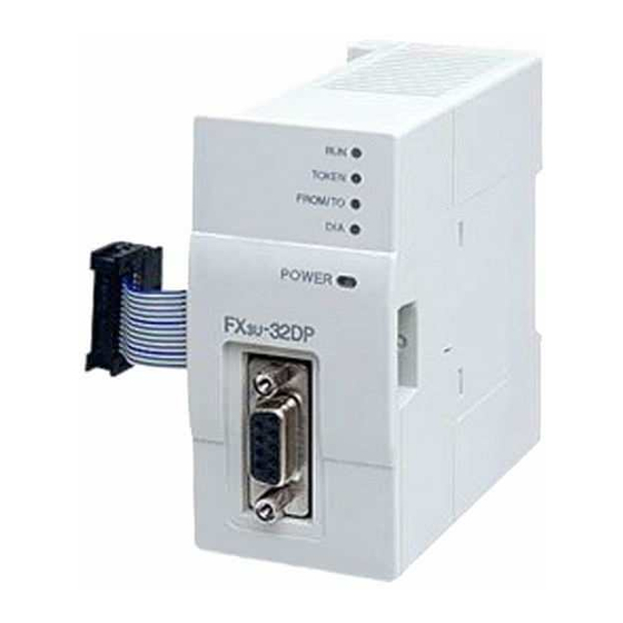
1.2 External Dimensions and Part Names
[3]
[4]
[2]
32
[1]
2-4.5
4 (0.16")
Tests
43 (1.7")
[1]
PROFIBUS-DP port (9-pin D-SUB Connector: #4-40unc inch screw thread)
[2]
Extension cable
Direct mounting hole:2 holes of 4.5 (0.18") (mounting screw: M4 screw)
[3]
[4]
Status LED
LED Name
Color
ON: Correct power supply from the PLC
POWER
Green
FROM/TO
Green ON: Constant FROM/TO access within 200ms intervals
ON: In cyclic data exchange mode
RUN
Green
Flashing: DP-Master is in clear mode, or DP-Slave is in
OFF: Normal Operation without errors
Otherwise: An error detected
DIA
Red
TOKEN
Green ON: Estabilished connection with the DP-Master
[5]
Extension port under the top cover
[6]
Name plate
[7]
DIN rail mounting groove (DIN rail: DIN46277)
[8]
DIN rail mounting hook
1.3 Pin configuration of PROFIBUS-DP Connector
The connector is a 9-pin D-SUB (#4-40unc inch screw thread) type, with the following
pin assignment.
Pin No.
3
4
5
6
8
1, 2, 7, 9
Assigned
Not assigned
2. Installation
INSTALLATION
*1
*1
*2
*2
/FX
/FX
/FX
/FX5U
/FX5UC
PLC
3GC
3U
3UC
PRECAUTIONS
*1
*2
*2
3U
/FX
3UC
/FX5U
/FX5UC
PLC with
Cut off all phases of the power supply externally before installation or wiring
work in order to avoid damage to the product or electric shock.
-32DP User's Manual
3U
INSTALLATION
PRECAUTIONS
-32MT-LT(-2).
3UC
Use the product within the generic environment specifications described in
the PLC main unit manual (Hardware Edition).
Never use the product in areas with excessive dust, oily smoke, conductive
dusts, corrosive gas (salt air, Cl
vibration or impacts, or expose it to high temperature, condensation, or rain
Included Item
and wind.
1 unit
If the product is used in such conditions, electric shock, fire, malfunctions,
deterioration or damage may occur.
1 piece
Install the product securely using the DIN rail or screws.
1 sheet
Install the product on a flat surface. If the mounting surface is rough, undue
force will be applied to the PC board, thereby causing nonconformity.
1 sheet
When drilling screw holes or wiring, make sure or cutting or wire debris does
1 manual each
not enter the ventilation slits.
Failure to do so may cause fire, equipment failures or malfunctions.
Be sure to remove the dust proof sheet from the PLC's ventilation slits when
installation work is completed.
[5]
[6]
Failure to do so may cause fire, equipment failures or malfunctions.
Connect the extension cables and communication cables securely to the
designated connectors. Contact failures may cause malfunctions.
Do not touch the conductive parts of the product directly to avoid failure or
malfunctions.
2.1 Connection with PLC
[7]
The FX
-32DP connects on the right side of a PLC main unit or extension unit/
3U
block (including special function units/blocks).
An FX
-CNV-IF or FX
2NC
FX
3GC
/FX
3UC
FX
-32MT-LT(-2).
3UC
[8]
An FX5-CNV-BUS or FX5-CNV-BUSC is necessary to connect to the 32DP with
the FX5U/FX5UC PLC.
9 (0.36")
For details, refer to the respective PLC manual.
87 (3.43")
89 (3.51")
Dimensions: mm (inches)
MASS (Weight): Approx. 0.2 kg (0.44 lbs)
2.2 Mounting
The 32DP can be mounted on a DIN rail (DIN46227) or mounted directly to the
mounting surface with screws.
Description
For other status, refer to FX
-32DP
3U
User's Manual
2.2.1
Direct Mounting
The 32DP can be directly mounted with M4 screws.
An interval space of 1 to 2 mm (0.04" to 0.08") between each unit is necessary.
Fail/Safe state.
2.2.2
DIN Rail Mounting
For error details, refer to FX
-32DP
The 32DP can be mounted on a DIN rail (DIN46227, 35mm width).
3U
User's Manual
1) Fit the upper edge of the DIN rail mounting
groove (right fig. A) onto the DIN rail.
2) Push the product onto the DIN rail.
Signal Name
Meaning
RXD/TXD-P
Receive/Transmit-Data-P
RTS
Ready to send
DGND
Data Ground
VP
Voltage-Plus (5V, 90mA)
RXD/TXD-N
Receive/transmit-Data-N
NC
Pin not assigned
2
, H
2
S, SO
2
or NO
2
), flammable gas,
-1PS-5V is necessary to connect to the 32DP with the
3UC
Series PLC. However, the 32DP cannot be connected to the
FX
Series User's Manual - Hardware Edition
3G
FX
Series User's Manual - Hardware Edition
3GC
FX
Series User's Manual - Hardware Edition
3U
FX
3UC
Series User's Manual - Hardware Edition
MELSEC iQ-F FX5U User's Manual (Hardware)
MELSEC iQ-F FX5UC User's Manual (Hardware)
FX
Series User's Manual - Hardware Edition
3G
FX
Series User's Manual - Hardware Edition
3GC
FX
Series User's Manual - Hardware Edition
3U
FX
3UC
Series User's Manual - Hardware Edition
MELSEC iQ-F FX5U User's Manual (Hardware)
MELSEC iQ-F FX5UC User's Manual (Hardware)
For details on the mounting hole pitch, refer to Section 1.2
1)
A
2)
Advertisement
Table of Contents

Related Manuals for Mitsubishi FX3U-32DP


Summary of Contents for Mitsubishi FX3U-32DP
- Page 1 How to obtain manuals -32DP 1 unit If the product is used in such conditions, electric shock, fire, malfunctions, For product manuals or documents, contact with the Mitsubishi Electric dealer you deterioration or damage may occur. GSD file (CD-ROM) 1 piece purchased your product.
- Page 2 (1) Damages caused by any cause found not to be the responsibility of Mitsubishi. -32DP at one PLC (2) Loss in opportunity, lost profits incurred to the user by Failures of Mitsubishi products. -32DP Do not touch any terminal while the PLC's power is on.
- Page 3 (1) Damages caused by any cause found not to be the responsibility of Mitsubishi. -32DP at one PLC (2) Loss in opportunity, lost profits incurred to the user by Failures of Mitsubishi products. -32DP Do not touch any terminal while the PLC's power is on.
Need help?
Do you have a question about the FX3U-32DP and is the answer not in the manual?
Questions and answers