Advertisement
Quick Links
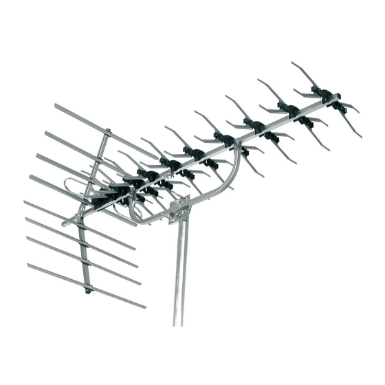
High Gain Wideband Digital Aerial
27884LAB
USER GUIDE
Congratulations on the purchase of your high gain wideband aerial which is designed to receive both analogue and digital terrestrial signals.
This aerial has been manufactured to the standard required to get the best reception of digital terrestrial TV services (such as Freeview™). If the
aerial is to be used for DTT reception check before installation at www.dtg.org.uk/retailer/coverage to confi rm that your home is in a coverage area
and to fi nd where your local transmitter is. For optimum results install the aerial using double screened digital coax cable and screened coax outlets.
Main Features
•
Wideband - suitable for all UK TV reception areas, covering UHF channels 21 to 68
•
Receives both digital and analogue TV signals
•
Perfect for use in the majority of locations although in very high strength signal areas an
attenuator may be required, or for very weak strength signal areas an amplifi er may be needed
The aerial requires some assembly - please read these instructions carefully before beginning.
A. Fitting the dipole assembly
The dipole clips onto the central boom. Ensure that the cable
exit hole (from the terminal box) faces the rear of the aerial
and that the locating stud fi ts into the locating hole on the
boom as shown in Fig. 1.
B. Rotating aerial elements, central
boom and centre mount assembly
1. Rotate the elements about the central fi xing clip until they
'snap' into an upright position as shown in Fig. 2.
2. The central boom comes in two sections using the bracket supplied and the
holes drilled in the boom sections join these two sections as shown in Fig. 3.
3. Attach centre mount bracket in the position shown using the clips supplied.
Fig. 2
rotate elements
C. Fitting the refl ectors
1. Using the refl ector clamps, screw and large wing nut, fi x
the refl ector assemblies to the main aerial boom.
2. Check that the refl ector clamp tabs locate in the holes
of the refl ector boom sections and that the wing nut
is tight - see Fig. 4.
2. Ensure that the refl ector elements are facing towards the
front of the aerial (convex surface forward).
rear of aerial
Fig. 1
locating
hole
Fig. 3
element
in upright
position
joining bracket with
bolts and wing nuts
locating stud
central boom
central boom
back section
central boom
front section
centre mount bracket
with clips, bolts and
wing nuts
refl ector boom
assembly
refl ector
element
Fig. 4
engage
tab
in hole
dipole
refl ector
clamps
Advertisement

Subscribe to Our Youtube Channel
Related Manuals for Labgear 27884LAB


Summary of Contents for Labgear 27884LAB
- Page 1 High Gain Wideband Digital Aerial 27884LAB USER GUIDE Congratulations on the purchase of your high gain wideband aerial which is designed to receive both analogue and digital terrestrial signals. This aerial has been manufactured to the standard required to get the best reception of digital terrestrial TV services (such as Freeview™). If the aerial is to be used for DTT reception check before installation at www.dtg.org.uk/retailer/coverage to confi...
- Page 2 10mm centre wire braid Coax plug wiring instructions 1 Unscrew coax plug housing and slide cap over cable. 2 Strip 23mm of cable outer sheath. Gather copper braid, wrap around outer sheath, slide claw over braid and crimp. 3 Strip 18mm of inner insulation to leave 5mm exposed 4 Undo screw on plug/clamp, slide clamp over inner wire &...
Need help?
Do you have a question about the 27884LAB and is the answer not in the manual?
Questions and answers