Advertisement
Quick Links
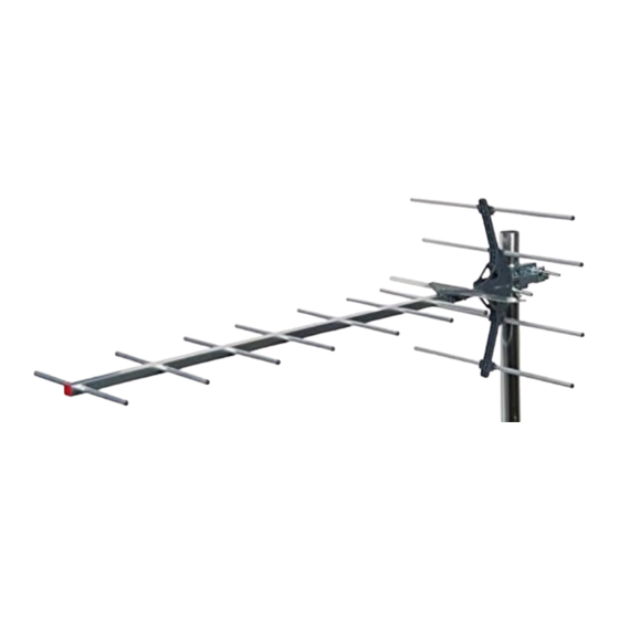
12 Element Digital Group A Aerial
LABGT12A
USER GUIDE
Congratulations on the purchase of your LABGT12A aerial. The aerial is ideal for the reception of
Group A signals in strong and medium strength areas. The aerial design has been tuned to
maximise reception of channels 21 - 37 and reject signals on other frequencies including signals
from Lte800 4G mobile phone transmitters which can interfere with digital TV channels.
Features include:
• 12dBi Gain
• F type connector for secure and easy connection
• Fast simple assembly
• Compact pack for easy transportation
Installation Instructions
For optimum results install the aerial using double screened CAI benchmarked digital
coax cable and screened coax outlets. You will need to fit the coax cable with the F type
connector supplied to connect to the downlead (not supplied)
to the F socket on the aerial.
1. Prepare the Coax Cable: Firstly fit the rubber weather boot
provided, to the aerial end of the cable. Strip the end of the
cable as shown in Fig. 1. Once you have stripped the cable,
twist the braid and pull it back on itself, make sure that no
braid is touching the copper core, this will cause a short on
the cable and you will not get any signal.
2. Fitting the F connector: Now, simply twist on
the 'F' connector supplied and trim the central conductor.
For best results the aerial should be mounted on an outdoor aerial mast and pointed in the direction of the nearest
transmitter* making sure it is in a position where the transmitter signal will not be obstructed by nearby trees and buildings.
If you are in any doubt about the direction in which the aerial should be pointing or the orientation of the aerial (horizontal for
main transmitter, vertical for relay transmitter) check your neighbours' aerials.
The aerial requires some assembly.
If mounting on an existing mast check that the mast is in good condition and firmly fixed.
Fitting the reflectors
3. Slide the reflectors into the
sockets mounted on the
central boom until they click
into place as shown in Fig. 3.
Fig. 1
cut or tear
away foil
fold braid back
over sheath
Fig. 2
screw connector
body onto cable
Fig. 3
reflector boom
assembly
reflector
element
Lte
800
READY
8mm
inner
wire
6.5mm
end of insulation
should be flush
with this face
2mm approx.
Advertisement

Related Manuals for Labgear LABGT12A


Summary of Contents for Labgear LABGT12A
- Page 1 LABGT12A USER GUIDE Congratulations on the purchase of your LABGT12A aerial. The aerial is ideal for the reception of Group A signals in strong and medium strength areas. The aerial design has been tuned to maximise reception of channels 21 - 37 and reject signals on other frequencies including signals from Lte800 4G mobile phone transmitters which can interfere with digital TV channels.
- Page 2 Fig. 4 4. If not already in position slide the mast clamp on to the aerial boom and then slide the clamp into position on the mast. Make sure the aerial is pointing in the direction of the nearest TV transmitter now tighten the wing nuts until the aerial is securely fixed into position, see Fig.
Need help?
Do you have a question about the LABGT12A and is the answer not in the manual?
Questions and answers