
Subscribe to Our Youtube Channel
Related Manuals for Pelican PEARL


Summary of Contents for Pelican PEARL
- Page 1 Pelican Wireless Systems Installation Guide PEARL Economizer Controller Pelican Wireless Systems, 2655 Collier Canyon Rd. Livermore, CA 94551 Phone: 888.512.0490 Email: support@pelicanwireless.com Website: www.PelicanWireless.com...
- Page 2 Compatibility The PEARL is an add-on accessory to the Pelican thermostat (TS200 or TS250). It provides inputs, outputs and logic that allow for intelligent economization and demand ventilation control. The PEARL is designed to control most 24VAC HVAC systems, including: gas, electric, oil, heat pump, and forced air. It is also designed to control 0-10VDC variable speed fans and modulating economizer damper actuators.
-
Page 3: Table Of Contents
Table of Contents Installation and Mounting Wiring Start Up Status Lights Actuator Calibration Setup and Configuration Troubleshooting Sequence of Operations... - Page 4 PEARL module (WM500) from Gently push WM500 all the way the thermostat base into the PEARL. Install jumper Loosen the R and Rc terminals between R and Rc and tighten. to remove the jumper (save Tighten R, C, D terminals on jumper).
- Page 5 Record which wires used for faceplate’s electrical board with each terminal. These wires will the three pin female connector connect to the same terminals on the thermostat sub-base. at the PEARL. Gently press the thermostat front plate onto the mounted sub-base.
- Page 6 8. Install the PEARL inside the HVAC equipment The PEARL should be mounted inside the HVAC equipment or enclosed in a water tight location. Mount in a location with easy access to control wiring and Pearl Economizer Controller service. DATA...
-
Page 7: Wiring
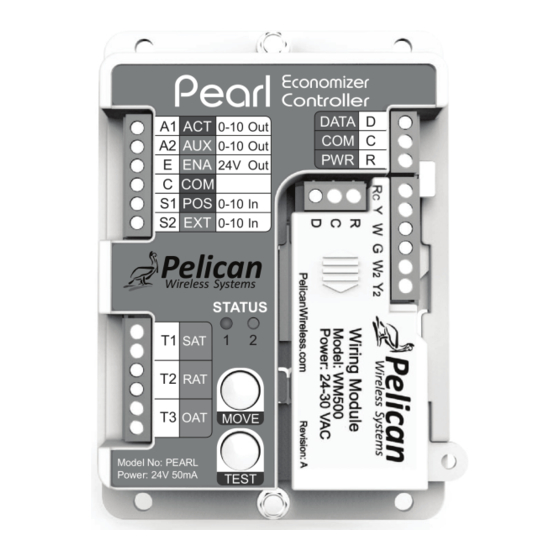
The PEARL has three terminal blocks. Refer to the following charts and wiring diagrams for proper connections. Pearl Economizer Controller DATA 0-10 Out Left-Top 0-10 Out Right Terminal Block 24V Out Terminal Block 0-10 In R C D 0-10 In... - Page 8 Conventional Control (Right Terminals) Heat Pump Control (Right Terminals) DATA DATA COMMON COMMON 24VAC PWR 24VAC PWR 24VAC 24VAC COOL STAGE 1 COMPRESSOR STAGE 1 HEAT STAGE 1 REVERSING VALVE (O/B) FAN or 24V VFD ENABLE FAN or 24V VFD ENABLE HEAT STAGE 2 AUXILIARY HEAT COOL STAGE 2...
- Page 9 Conventional Unit Wiring (Right Terminal Block) ROOF TOP UNIT Pearl Economizer Controller DATA 0-10 Out 0-10 Out 24V Out 0-10 In R C D 0-10 In Pelican Wireless Systems STATUS NOTE: "G" 24V output can also be used to enable a VFD.
- Page 10 Heat Pump Unit Wiring (Right Terminal Block) ROOF TOP UNIT Pearl Economizer Controller DATA 0-10 Out 0-10 Out 24V Out 0-10 In R C D 0-10 In Pelican Wireless Systems STATUS NOTE: "G" 24V output can also be used to enable a VFD.
- Page 11 Economizer Actuator Wiring (Left-Top Terminal Block) Connect actuator power to the same 24VAC power source as the PEARL. Pearl Economizer Controller DATA 0-10 Out 0-10 Out Economizer Actuator 24V Out - Common + Hot 0-10 In R C D 0-10VDC In...
- Page 12 Variable Frequency Drive (VFD) Wiring (Left-Top Terminal Block) Connect VFD Common to the same Common as the PEARL. Pearl Economizer Controller DATA 0-10 Out 0-10 Out 24V Out Common 0-10 In R C D 0-10VDC In 0-10 In 24V Fan Enable...
- Page 13 24VAC Economizer Enable Output (Left-Top Terminal Block) The “E” terminal is energized whenever the Economizer is active and can be used to control exhaust fans or auxiliary economizer equipment. Pearl Economizer Controller DATA 0-10 Out 0-10 Out Exhaust Fan 24V Out...
- Page 14 10K Type 2 Thermistor Wiring (Left-Bottom Terminal Block) Supply Probe (10K Type 2) Pearl Economizer Controller DATA 0-10 Out Return Probe (10K Type 2) 0-10 Out (optional) 24V Out 0-10 In R C D 0-10 In Pelican Wireless Systems STATUS...
- Page 15 Option 1) Install Outside Air Probe Inside PVC Enclosure Inside HVAC Economizer Air Intake Hood unit PEARL Mount outside air probe inside a weather resistant, sun shielded PVC enclosure directly outside of Air Intake Hood. Option 2) Install Outside Air Probe Inside the Air Intake Hood...
-
Page 16: Start Up
Start Up Restore power to the HVAC equipment. The PEARL will need to be calibrated and configured to work with the HVAC system and must conform to local and state codes and ordinances. If being installed as part of a Utility program, the PEARL must be configured to meet all requirements for that program. -
Page 17: Status Lights
PEARL is unable to communicate with thermostat. Verify R, C, D terminals are tightly screwed down at Blinking PEARL and thermostat. Check that the R, C, D wires match from PEARL to thermostat. Damper Position Error Damper feedback is indicating incorrect position. - Page 18 Testing the Actuator with the Move Button Before configuring the PEARL, it is easy to test if the economizer actuator is correctly wired to the PEARL (A1) output terminal and to verify damper movement. When powered ON (A1) will output 2.0 VDC.
- Page 19 To use the Automated One-Touch Configuration process you must have an economizer actuator with a position feedback output wired to the S1 terminal on the PEARL. At this time you will also want to set any manual actuator stops if required.
- Page 20 Test started blinking blinking 4. After approximately 60 seconds Status light 2 (blue light) will begin flashing to indicate the PEARL is moving the damper to the FULLY CLOSED position. Closing economizer damper flashing If the economizer damper begins OPENING during Step 5 then press the button to switch to closing the damper.
-
Page 21: Troubleshooting
PEARL is unable to communicate with thermostat. Verify R, C, D terminals are tightly screwed down at Solid the PEARL and thermostat. Check that the R, C, D wires match from PEARL to thermostat. No Communication PEARL is unable to communicate with thermostat. -
Page 22: Sequence Of Operations
Pelican Wireless Systems Sequence of Operation Overview The Pearl Economizer Controller provides automated control of HVAC Economizers and associated equipment. The controller has built-in logic to: − Deliver cool outdoor air to reduce the need for mechanical cooling. − Provide necessary ventilation in commercial buildings. - Page 23 Controller Inputs/Outputs HVAC Signals Y, Y2, G, W, W2, O/B 24VAC – Industry standard 24VAC signal outputs directly control up to 2 stages of Heat and 2 stages Cool for both Conventional and Heat Pump systems. Auxiliary and Emergency Heat are also supported. Economizer Signals 0-10 VDC Actuator Output –...
- Page 24 Thermostat Inputs Integrated Room Temperature Sensor: -20 °F – 128 °F with 0.1 °F resolution (Model TS200) Integrated CO2 sensor: 0 – 2000 ppm +/- 50 ppm accuracy, 1 ppm resolution (Model TS250) Integrated Humidity sensor: 0 – 100% RH (Model TS200H or TS250H) Supplied Online Data Outside Relative Humidity - local humidity levels based on...
- Page 25 Input/Output Wiring All interconnect wiring for Thermostats, Pearl Controller, Optional Sensors, Actuators and HVAC signals can be done with standard 18 AWG solid thermostat wire or similar. Location of Components in an Economizer System.
- Page 26 Configuration Parameters Range Default Parameter Automatic or Automatic High Limit Temperature 30°F – 90°F (blank) Maximum outside temperature to allow active economization. 0°F – 6°F 2°F Differential Limit Economizer is only enabled if the outside temperature is at least this many degrees below the room space temperature.
- Page 27 Range Default Parameter Temperature, Input Sensor T1 Supply Temp Monitor, Temperature 10K type 2 temperature sensor input, dry Alarm, contact alarm input, or dry contact occupancy Occupancy input. Temperature, Input Sensor T2 Return Temp Monitor, Temperature 10K type 2 temperature sensor input, dry Alarm, contact alarm input, or dry contact occupancy input.
- Page 28 Thermostat Control Thermostat sequence of operation is outside the scope of this guide. However, the operation of the Pearl Economizer Controller is directly tied to the thermostat's decision to enable Heating, Cooling or Ventilation. These decisions are based on thermostat...
- Page 29 c. Fixed Enthalpy Limit – If enabled, the Economizer is only active if the outside air enthalpy is below 28 Btu/lb or at higher elevations below the calculated enthalpy at 75°F and 50% relative humidity at that elevation. 2. Activation – The economizer will be activated if the thermostat logic is calling for cooling and the conditions in item 1 are satisfied.
- Page 30 Economizer Faults The controller continually monitors inputs to verify proper operation. When a fault is detected it will be displayed as a notification on the Web-App control console. In addition, the notification will be sent to an unlimited list of designated service personnel via email and Text Message.
- Page 31 6. Cool/Heat Failure – A fault will be generated if the equipment is unable to heat or cool the conditioned space. Ventilation Control The Pearl Economizer Controller supports multiple Ventilation modes depending on installed equipment and the desired ventilation strategy. These modes are: 1.
- Page 32 Fan set to “On”. During this time ventilation will be delivered based on the “Minimum Damper Position”. 6. Demand Ventilation – The Pearl Economizer Controller will provide demand ventilation when installed with a Pelican thermostat which has an integrated CO2 sensor (Model TS250 or TS250H).
- Page 33 Variable Speed Fan The Pearl Economizer Controller can control a Variable Speed Fan or Variable Frequency Drive (VFD). 1. Activation – This function is only active if the “Variable Speed Fan”...
- Page 34 THIS PAGE INTENTIONALLY LEFT BLANK...
- Page 35 THIS PAGE INTENTIONALLY LEFT BLANK...
- Page 36 Pelican Wireless Systems. All Rights Reserved. For More Information Please Visit: www.pelicanwireless.com Pelican Wireless Systems, 2655 Collier Canyon Rd. Livermore, CA 94551 Phone: 888.512.0490 Email: support@pelicanwireless.com Website: www.PelicanWireless.com 37-0004...
Need help?
Do you have a question about the PEARL and is the answer not in the manual?
Questions and answers