Advertisement
Quick Links
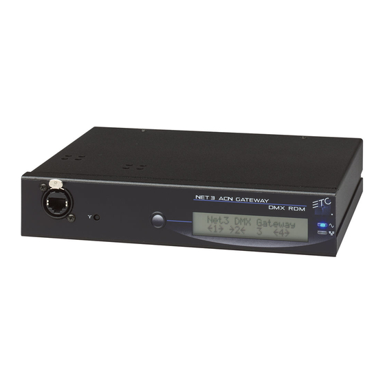
Four-Port Gateway Setup Guide
Overview
This Setup Guide will guide you through the setup of the Net3 Four-Port DMX/RDM gateway including hardware, electrical and
data connections. Software configuration of your gateway is covered separately and relates specifically to the software versions
that may be running in the gateways.
• For Net3 configuration, please refer to the Gateway Configuration Editor (GCE) Online Help System.
• For use on ETCNet2 systems, use the ETCNet2 Network Configuration Editor (NCE) User Manual which includes information
about the Net3 DMX Gateways running in ETCNet2 mode.
Ethernet Connection
• PoE (IEEE 802.3af)
Menu Button
• 10/100Mbps data speeds
• Activates the LCD backlight
• Auto-sensing
• Advances display pages
• Auto-negotiation
• RJ45 and etherCON compatible
Push
Reset Button
LCD
• hard reboot
• Displays gateway status
and configuration data
Strain Relief
Four Module Bays
• strain relief clip for
• use any combination of modules
including the blank plate, DMX
Out (XLR Female), DMX In (XLR
Male), RJ45 and terminal strip
modules.
Corporate Headquarters 3031 Pleasant View Road, P.O. Box 620979, Middleton, Wisconsin 53562-0979 USA Tel +608 831 4116 Fax +608 836 1736
London, UK Unit 26-28, Victoria Industrial Estate, Victoria Road, London W3 6UU, UK Tel +44 (0)20 8896 1000 Fax +44 (0)20 8896 2000
Rome, IT Via Ennio Quirino Visconti, 11, 00193 Rome, Italy Tel +39 (06) 32 111 683 Fax +44 (0) 20 8752 8486
Holzkirchen, DE Ohmstrasse 3, 83607 Holzkirchen, Germany Tel +49 (80 24) 47 00-0 Fax +49 (80 24) 47 00-3 00
Hong Kong Rm 1801, 18/F, Tower 1 Phase 1, Enterprise Square, 9 Sheung Yuet Road, Kowloon Bay, Kowloon, Hong Kong Tel +852 2799 1220 Fax +852 2799 9325
Service: (Americas)
service@etcconnect.com
(UK)
Web:
www.etcconnect.com
Copyright © 2010 ETC. All Rights Reserved. Product information and specifications subject to change.
4260M2200
Revision D
2010-01
Power Indicator
• Solid blue LED
indicates power
Activity Indicator
• Solid green LED indicates
network connection.
• Flashing LED indicates
network activity
DC Power Input
• 8-28Vdc
• Positive tip
dc power cable
• 3.5mm barrel
• 5 Watts usage
Power Indicator
• Solid blue LED
indicates power
Activity Indicator
Grounding Post
• Solid green LED indicates
network connection.
• Flashing LED indicates network
activity
service@etceurope.com
(DE)
techserv-hoki@etcconnect.com
(Asia)
service@etcasia.com
DMX Gateway Modules
DMX Termination
• switch directly behind the
connector for convenience
Protective Cover
• protects delicate
electronics
DMX Out Module
(XLR 5-pin female)
There are four different modules available for use in the Four-Port gateway: DMX Out (5-pin female), DMX In (5-pin male),
RJ45 (8-pin female for input or output) and DMX Terminal Strip (8-pin Weidmuller for input or output).
• The terminal strip module comes with ETC's standard DMX termination preparation kit (part number 4100A1012) which includes instructions and
all parts required for installation. If you are connecting to Category 5 wire for DMX, request the DMX termination preparation kit with IDC
connectors from ETC (part number 4100A1013).
• The DMX RJ45 module can use a standard Category 5 cable to transmit DMX512 to other devices utilizing the same connector.
NOTE:
The DMX RJ45 module will not function as an Ethernet network port.
Any of these modules may be configured as DMX input or DMX output using configuration software. Additionally, there is a blanking plate for any
unused module bay.
WARNING:
RISK OF ELECTRIC SHOCK! Power must be removed from the gateway before removing any modules or covers to
service the unit.
With power removed from the Gateway, you can move and swap DMX modules as needed for required configuration or replacement.
Help from ETC Technical Services
If you experience difficulty during setup or installation of the Net3 gateway, additional information is available from www.etcconnect.com, or by
contacting ETC Technical Services at your local office listed on the bottom left side of this document.
DMX Basics and Pin-Outs
The Net3 Four-Port gateway sends and receives DMX512 control signals. This unit can contain up to four DMX ports in any combination
using 5-pin DMX input connectors, 5-pin DMX output connectors, RJ45 connectors, or terminal strip connectors. DMX cables must be
acceptable for DMX data transmission (not microphone cable) and connections should follow the standard pinouts per the charts below.
The optional secondary data pair is not used by the Net3 Four-Port gateway.
DMX512 Pinout for 5-pin XLR Connectors
Female (output)
Pin#
Use
Male (input)
Common
1
Push
(shield)
2
Data -
3
Data +
5
1
1
5
4
2
2
4
4
unused
3
3
5
unused
Page 1 of 2
DMX RJ45 Module
(RJ45 8-pin female)
Retaining Screw
• secures the module
in the gateway
Pull Tab
• for easy module removal
DMX Terminal
Strip Module
(8-pin male)
DMX512 Pinout for Terminal Strip Connector
DMX512 Pinout for RJ45 Connectors
Female
Pin#
Use
Wire Color
Female
Data 1 +
White/Orange
1
2
Data 1 -
Orange
Push
not used
White/Green
3
1
4
not used
Blue
1
8
not used
White/Blue
5
6
not used
Green
7
Signal Common
White/Brown
8
Signal Common
Brown
DMX In Module
(XLR 5-pin male)
Pin#
Use
Wire Color
1
Common (shield)
Clear/Shield
2
Data -
Black
3
Data +
Red
8
4
unused
5
unused
6
unused
7
unused
8
unused
Advertisement

Related Manuals for ETC Net 3


Summary of Contents for ETC Net 3
- Page 1 • PoE (IEEE 802.3af) Menu Button • The terminal strip module comes with ETC’s standard DMX termination preparation kit (part number 4100A1012) which includes instructions and • 10/100Mbps data speeds all parts required for installation. If you are connecting to Category 5 wire for DMX, request the DMX termination preparation kit with IDC •...
-
Page 2: Menu Structure
Occasionally a DMX device can encounter an electrical surge that causes the DMX transceiver chip to fail. This DMX chip (mfg# 75LBC182 / ETC# Z1458-F) is located under the cover next to the termination switch. As needed, you can •...