Advertisement
Quick Links
Two-Port Gateway Installation Guide
Overview
This Installation Guide will lead you through the setup of the Net3 Two-Port DMX/RDM gateway
(version 5.x software and later) including hardware, electrical and data connections. Software
configuration of your gateway is covered separately and relates specifically to the software versions that
may be running in the gateway.
• For configuration, please refer to the Gateway Configuration Editor (GCE) Online Help System.
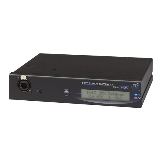
Activity Indicator
Power Indicator
• Solid green LED indicates
network connection.
• Solid blue LED
indicates power
• Flashing LED indicates
network activity
Menu Button
• Activates the
LCD backlight
• Advances
display pages
Reset button
• hard reboot
DC Power input
• 8-28Vdc
• <5 Watts usage
Corporate Headquarters 3031 Pleasant View Road, P.O. Box 620979, Middleton, Wisconsin 53562-0979 USA Tel +608 831 4116 Fax +608 836 1736
London, UK
Rome, IT Via Pieve Torina, 48, 00156 Rome, Italy Tel +39 (06) 32 111 683 Fax +44 (0) 20 8752 8486
Holzkirchen, DE Ohmstrasse 3, 83607 Holzkirchen, Germany Tel +49 (80 24) 47 00-0 Fax +49 (80 24) 47 00-3 00
Hong Kong Rm 1801, 18/F, Tower 1 Phase 1, Enterprise Square, 9 Sheung Yuet Road, Kowloon Bay, Kowloon, Hong Kong Tel +852 2799 1220 Fax +852 2799 9325
Service: (Americas)
service@etcconnect.com
Web:
www.etcconnect.com
Copyright © 2012 ETC. All Rights Reserved. Product information and specifications subject to change.
4261M2201
Revision B
2012-05
ETC intends this document to be provided in its entirety.
LCD
• Displays gateway status
and configuration data
DMX Ports
• Pair of XLR 5-pin DMX Output
(female) or DMX Input (male)
connectors.
Ethernet
• PoE (IEEE 802.3af)
• 10/100Mbps data speeds
• Auto-sensing
• Auto-negotiation
Termination
• DMX termination
switches
Tel +44 (0)20 8896 1000 Fax +44 (0)20 8896 2000
(UK)
service@etceurope.com
(DE)
techserv-hoki@etcconnect.com
(Asia)
service@etcasia.com
Installation Requirements
• Installation location - the Two-Port gateway fits into an industry standard 2-gang deep back box (provided by others) or surface-mount back box
(available by ETC).
• Power - can be powered by either Power over Ethernet (PoE 802.3af) or by use of an external dc power supply. Using PoE and dc power simultanously
is not supported. Power consumption is less than 5 Watts.
•
For Power over Ethernet (IEEE 802.3af), connect to the RJ45 receptacle on the rear panel of the gateway. This connection point supports PoE,
auto-sensing, auto-negotiation and 10/100Mbps data speeds. All Ethernet wiring must comply with IEEE 802.3 and be terminated to the T568B
standard.
•
For DC power input (external power supply 8-28 Vdc), connect to the two pin pluggable header provided on the rear panel of the gateway.
•
An optional Universal Power Supply (ETC part number PS313-F) 90-240V AC to 12 Vdc @ 1.3 A is available for use with portable and rack mount
gateways. Contact your ETC Customer Service Representative for details.
• Network Data and DMX - the Two-Port gateway complies with 802.3i for 10BASE-T, 802.3u for 100BASE-TX and 802.3af for Power over Ethernet
specifications. Data transport utilizes the TCP/IP suite of protocols and distributes DMX over Ethernet to any input/output device.
Ethernet is connected to the RJ45 connector on the rear panel of the unit.
•
•
The Two-Port gateway is capable of supporting 1024 DMX In or DMX Out channels utilizing the two built-in DMX ports. The DMX ports can be
either two XLR-5pin Male DMX input connectors or two XLR-5pin Female output connectors. Termination switches are provided on the rear panel
for user convenience.
See page 2 of this document for more information on DMX and termination
Installation
WARNING: RISK OF ELECTRICAL SHOCK! Power must be removed from the gateway before removing or servicing the unit.
Step 1
On
On
Step 1: Use the provided screws to secure the mounting bracket to the two gang back box.
NOTE: This mounting bracket fits standard masonry wall back boxes, surface-mount boxes, and portable enclosures.
Step 2: Connect the power and data to the rear panel of the unit.
Step 3: If necessary, set the DMX termination using the termination switches located on the rear panel of the unit. S1 controls the
termination for Port 2 and S2 controls the termination for Port 1. By default termination is set to "On". For most applications no
change to the default will be required.
Step 4: Install the Two-Port gateway to the mounting bracket on the back box.
a:
Align the top tabs on the Two-Port gateway to the receptacles on the mounting bracket.
b:
Swing the bottom of the gateway down and hold it in place.
Step 5: Secure the Two-Port to the mounting bracket using the two screws on the bottom panel of the unit, next to the DMX ports.
Page 1 of 2
switches.
Step 4.a
Step 2
Step 3
Step 4.b
Step 5
Advertisement

Related Manuals for ETC NET 3


Summary of Contents for ETC NET 3
- Page 1 For DC power input (external power supply 8-28 Vdc), connect to the two pin pluggable header provided on the rear panel of the gateway. • An optional Universal Power Supply (ETC part number PS313-F) 90-240V AC to 12 Vdc @ 1.3 A is available for use with portable and rack mount gateways. Contact your ETC Customer Service Representative for details.
- Page 2 00:C0:16:00:00:1A If you experience difficulty during installation of the Net3 gateway, additional information is available from www.etcconnect.com, or by contacting ETC Technical Services at your local office listed on the bottom left side of this document. Page 2 of 2...