Advertisement
Table of Contents
Advertisement
Table of Contents

Summary of Contents for EXTENDGROUP EKH-455
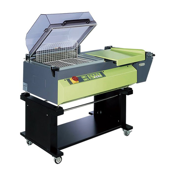
- Page 1 SHRINKING-WRAPPING MACHINE EKH-455 OPERATION & MAINTENANCE MANUEL 2013.08.01...
- Page 2 SAFETY INFORMATION Before attempting to service or use this machine carefully read this instruction manual. Please pay particular attention to features showing the WARNING SYMBOL: 1. DO NOT replace any safety parts of different Specifications 2. DO NOT use the machine in an atmosphere of high humidity 3.
-
Page 3: Table Of Contents
TABLE OF CONTENTS Machine description Packaging Machine assembly Specification Controls Setting –up procedure Operation General maintenance Routine maintenance Trouble shooting Parts list and exploded views 10~21 Electrical schematic... -
Page 4: Machine Description
MACHINE DESCRIPTION Our machine is a manually operated shrink PLEASE PAY PARTICULAR ATTENTION TO wrapping machine for use with PVC or THE FOLLOWING polyolefin shrink films It can be used either to make loose bags, or to LIMITS OF USE shrink the film tightly around your products by The machine must not be used in the following circulating heated air inside the hood. - Page 5 PACKING Machine is film wrapped for protection and packed for transport in corrugated sleeve and top, and secured to a pallet. Optional bag containing: Particular care must be taken in opening the -1spare sealing wire;(7-05000-250) case not to damage the machine sponge strip;...
-
Page 6: Machine Assembly
MACHINE ASSEMBLY STAND (see also Fig.1) MACHINE BODY(see also Fig2) ---Secure the 4castors to the stand base --Put the machine on the stand (ensuring section using the nuts provided, and position that the adjustable leveling feet locate in the the BRAKED castors at the FRONT of the cups on the UPRIGHT sections ).OR the stand machine on your bench if no machine stand... -
Page 7: Specification
SPECIFICATIONS OVERALL DIMENSIONS SPECIFICATIONS -Weight of machine (without stand): 85kg -Height of working table (on stand) 370mm -The machine height of working incl. stand 910mm -Dimensions of sealing:420×550 -Power:3.77kw Voltage: 230v/1-phase -packaging capacity: min: A×B×C 50×50×1mm max: A×B×C 520×390×250mm NOTES:B+C must never exceed 550;it is not possible to create packages with the maximum dimension A×B×C, -film to be used for packaging :center-fold sealing film, thickness 60 gauge. -
Page 8: Controls
CONTROLS MAIN SWITCH DIGITAL READOUT It shows the value of the every time setting. START SWITCH Press the key , the indicator lamp(1) will light, The machine starts heating HEATING INDICATOR and the machine is only for sealing .in When the machine temperature does any situation, press the key to make not reach the setting temperature, the lamp go out, you can stop the... -
Page 9: Setting -Up Procedure
Times are required to successfully shrink wrap SETTING –UP PRODEDURE Your produces. 6 Press the choosing key the third time 1. Set the MIAN SWITCH to position “ON”. (see page5) 5 will flash, Then using to adjust the cooling time: 2 .Press the button of START/STOP to make the show:00 means :sealing and shrinking is working at the same time. -
Page 10: Operation
OPERATION FILM SIZE/ADJUSTMENT The way to thread film: Select a suitable film width for your Adjust the position of the connector Product (-usually WIDTH OF PRODUCT (front shaft through pulling the sphere-type handle(the black sphere on the two side To back) and HEIGHT OF PRODUCT + about of connect shaft) to locate it at the 75mm), Fit the film on the reel carrier with the lowest point of the “... -
Page 11: General Maintenance
ROUTINE MAINTENANCE GENERAL MAINTENANCE It is advisable to use two qualified people for Operations to be carried out by the machine Maintenance . operator. BEFORE ATTEMPTION ANY The machine operates with plastic films MAINTENANCE TURN MAIN SWITCH OFF which may leave deposits on the sealing blade AND DISCONNECT POWER SUPPLY! and so effect quality CAUTION HOT!! CAUTION HOT!! -
Page 12: Trouble Shooting
TROUBLE SHOOTING THE HOOD WON’T STAY OPEN INCOMPLETE SEAL Torsion bar out of adjustment? Torsion bar broken ? Solution: Replace the torsion bar Solution: Check sealing blades and Teflon tape for cleanliness. Clean and THE HOOD WON’T STAY OPEN lubricant COMPLETELY With silicone. -
Page 13: Parts List And Exploded Views 10~21
PARTS LIST, FIGURE 1 ASSEMBLY OF THE STAND FPH-204-016 Q'TY PART NO. DESCRIPTION 7-01000-111 Upright 7-01000-121 Lower platform 229A075PU-BK Wheel,swivel 75mm 13.1 229C075PU-BK Wheel fixed 75mm 7-01000-140 Basket bracket shaft 200A08045 Socket head cap screw, M8*45 202A0816 Plain washer, M8*16 202B08 Lock washer, M8 201A08... - Page 14 FIGURE 1: ASSEMBLY OF THE STAND 13-1 WARNING All parts must be periodically inspected and replaced if worn or broken.Failure to do this can affect a tool's operation and present a safety hazard.
- Page 15 PARTS LIST,FIGURE 2-4 HOOD UNIT FPH-204-022 Q'TY PART NO. DESCRIPTION 7-02000-112 Hood 7-02000-120 Transparent hood seat I 12.1 7-02000-121 Transparent hood seat II 7-02000-130 Handle 7-05000-110 7-05000-120 Aluminum seat (long) 15.1 7-05000-121 Aluminum seat (short) 7-05000-130 Sponge strip(long) 16.1 7-05000-131 Sponge strip(short) 7-02000-200 Spring buckle...
- Page 16 FIGURE2-4: HOOD UNIT 12-1 15-1 110 24 16-1 15-1 WARNING All parts must be periodically inspected and replaced if worn or broken.Failure to do this can affect a tool's operation and present a safety hazard.
- Page 17 PARTS LIST,FIGURE 3-6 BASIN-RESISTOR UNIT FPH-204-038 Q'TY PART NO. DESCRIPTION 7-03000-110 Hinge 7-03100-120 Hinge adjustable support (L) 12.1 7-03100-121 Hinge adjustable support (R) 7-03000-141 Fin fasting board 7-03000-320D Heating tube,220-230VAC 900W 7-03000-160 Rear panel 7-03000-180 Anti-high tem.clothe 7-03800-200 Tray 7-03000-211 Tray uphold 7-03000-220 Heater transmission fastener...
- Page 18 FIGURE 3-6: BASIN - RESISTOR GROUP 12-1 WARNING All parts must be periodically inspected and replaced if worn or broken.Failure to do this can affect a tool's operation and present a safety hazard.
- Page 19 PARTS LIST, FIGURE 4 REEL CARRIERGROUP FPH-204-040 Q'TY PART NO. DESCRIPTION 7-04000-110 Separator 7-04000-120 Film holder body 7-04000-130 Spinder 7-04000-140 Rubber roller 7-04000-150 Shaft 7-04000-170 Click pulley 7-04000-180 Adjusting bracket 7-04000-190 Scored pulley fastener 7-04000-200 Connector shaft 7-04000-210 Lock wimble 7-04000-220 Film shaft 7-04000-230...
- Page 20 FIGURE 4: REEL CARRIER GROUP WARNING All parts must be periodically inspected and replaced if worn or broken.Failure to do this can affect a tool's operation and present a safety hazard.
- Page 21 PARTS LIST,FIGURE 5-8:SEALING BAR,TORSION SPRING,CABINET UNIT FPH-204-058 Q'TY PART NO. DESCRIPTION 7-05101 SEALING UNIT 7-05102 TORSION SPRING UNIT 7-05104 CABINET UNIT 7-05000-132 Sponge strip 7-05000-140 Heating row(long)565mm 14.1 7-05000-141 Heating row(short)515mm 7-02000-152 Body 7-02000-160 Bottom plate 7-05800-170 Heating row fastener I 7-05800-180 Heating row fastener II 7-05000-200...
- Page 22 14-1 23.1 121 126...
- Page 23 PARTS LIST,FIGURE 6-4 ELECTRICAL UNIT FPH-204-066 Q'TY PART NO. DESCRIPTION 7-06000-111 Electrical fixed board 7-06000-150 Connector nut PC-FP-70SB02 Show PC board .FP-70SB02 PC-FP-70B02 Control PC board asse.FP-70B02 4-10200-130 Bush 3-14000-170 Clip 201A05 Hex nut, M5 202B05 Lock washer, M5 202A0512 Plain washer, M5*12 202A0409 Plain washer, M4*9...
- Page 24 FIGURE6-4: ELECTRICAL UNIT 120 130...
- Page 26 -23-...
Need help?
Do you have a question about the EKH-455 and is the answer not in the manual?
Questions and answers