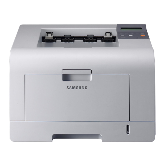
Samsung ML-3471ND/XAX Service Manual

Samsung ML-3471ND/XAX Service Manual

Ml-347x series
Table of Contents

Advertisement

Quick Links

SERVICE

LASER PRINTER

ML-347x Series
LASER PRINTER
ML-347x Series
ML-3471ND/XAX
Basic Model : ML-3471ND
Manual
The keynote of Product
Upgrade to Speed_up model(ML-347x)
of the ML-3050 serie
1. Speed: Up to 33ppm (Ltr. 35ppm),
1200x1200dpi Effective output
2. Paper Path: MPF Type Cassette
3. Emulation: PCL6, PS3
4. CPU: SPGPv3
5. Memory: 16~64MB Standard
6. Cassette: 250 sheet Cassette
7. MP: 50 sheet MP
8. Lan: 10/100 Base TX (ML-3471ND)
9. I/O: USB 2.0, IEEE1284
10. Toner: 10K Toner (4K initial)
11. Option: 802.11b/g Wireless N/W,
250 sheet Opt. SCF
12. Duplex: Built in Duplex

Advertisement

Table of Contents
loading

Summary of Contents for Samsung ML-3471ND/XAX

  • Page 1: Laser Printer

    LASER PRINTER ML-347x Series ML-3471ND/XAX Basic Model : ML-3471ND Manual SERVICE LASER PRINTER The keynote of Product Upgrade to Speed_up model(ML-347x) of the ML-3050 serie 1. Speed: Up to 33ppm (Ltr. 35ppm), 1200x1200dpi Effective output 2. Paper Path: MPF Type Cassette 3.
  • Page 2: Table Of Contents

    Contents 1. Precautions 1.1 Safety Warning 1.2 Caution for safety 1.3 ESD Precautions 2. Product spec and feature 2.1 Product Specifications 2.1.1 Product Overview 2.1.2 Specifications 2.1.3 Model Comparison Table 2.1.4 Accessory List 2.2 System Overview 2.2.1 System Construction 2.2.2 Mechanical Parts Specifications 2-12 2.2.3 Engine H/W Specifications 2-18...
  • Page 3 Continued 3.11 Drive Ass'y 3-15 3.12 Duplex Drive Ass'y 3-16 3.13 Shield SMPS Ass'y 3-17 3.14 Connection PCB 3-18 3.15 Fuser Drive Ass'y 3-19 3.16 Fan 3-20 3.17 Pick Up Roller Ass'y 3-21 3.18 Duplex Guide Housing (With Feed Roller) 3-22 3.19 HVPS Housing 3-23...
  • Page 4 Continued 4.2.3 The cause and solution of the bad discharge 4-40 4.2.4 The cause and solution of the malfunction 4-49 4.2.5 Toner Cartridge Service 4-59 4.2.6 The cause and solutions of bad environment of the software 4-64 5. Exploded Views & Parts List 5.1 Main 5.2 Cover Ass'y 5.3 Front Cover Ass'y...
  • Page 5 Continued 7.4 LAN (Optional Function) 7.5 Sample Tests Patterns 7.6 Series model solution(ML-3470D and ML-3471ND) 7.6.1 Double Feed Erro 7.6.2 Jam0 7.6.3 Jam1 7.6.4 No Paper/Add Paper" error on the printer and have been unable to clear it, even when they have verified there is paper in the printer 7.6.5 Open Cover Error 7-10 7.6.6 Low Toner...
  • Page 6: Precautions

    Warning >> Never operate or service the printer with the protective cover removed from Laser/Scanner assembly. The reflected beam, although invisible, can damage your eyes. When using this product, these basic safety precautions should always be followed to reduce risk of fire, electric shock, and injury to persons. Service Manual Samsung Electronics...
  • Page 7: Caution For Safety

    (12) Turn off the power and take off the plug when smoke, strange smell, or sound from the machine. If you keep using it, a fire can be occurred. (13) Do not insert steel or metal piece inside/outside of the machine. Do not put steel or metal piece into a ventila- tor. An electric shock could happened. Service Manual Samsung Electronics...
  • Page 8: Handling Precautions

    (7) Be careful not to change the location of small parts such as screws when assembling and disassembling. (8) Do remove dust or foreign matters completely to prevent fire of tracking, short, or etc. (9) After finished repair, check the assembling state whether it is same as before the repair or not. Service Manual Samsung Electronics...
  • Page 9: Esd Precautions

    9. Minimize bodily motions when handling unpackaged replacement ESDs. Normal motions, such as the brushing together of clothing fabric and lifting one’s foot from a carpeted floor, can generate static electricity sufficient to damage an ESD. Service Manual Samsung Electronics...
  • Page 10: Product Specifications

    Less than 15 sec, Cold warm-Up time : 15sec FPOT From Ready Less than 8.5 sec From Idle Less than 23.5 sec From Coldboot Less than 30 sec Resolution Up to 1,200 x 1,200 dpi effective output Service Manual Samsung Electronics...
  • Page 11 8.6 and aboverVarious Linux OS including Red Hat, Caldera, Debian, Mandrake, Slackware, SuSE and Turbo LinuxNovell 4.x,5.x,6.x Application Status Monitor Smart Panel YES (RCP,SM) Network Management SAS (Samsung Admin Service), SetIP Interface Parallel IEEE 1284 USB 2.0 Wired Network Ethernet 10/100 Base TX (Internal) Wireless Network Optional (Internal) 802.11b/g...
  • Page 12: Paper Handling

    Output Stacking Capacity Face-Down 150 sheets @ 75g/ Face-Up 1 sheet @ 75g/ Output Full sensing Duplex Supporting Built-in Media sizes A4, Letter, Legal, Folio, Oficio Media types Plain Paper Media weight 20~24lb (75 to 90g/ ) Service Manual Samsung Electronics...
  • Page 13 Less than 400W Max/Peak Less than 700W Sleep/Power Off Less than 11W / Less than 0.4W Dimension(W x D x H) 400 x 433.4 x 285 mm Weight 10.5 kg (23.15 Pounds) Gross 14.5kg (31.9 Pounds) Service Manual Samsung Electronics...
  • Page 14 ML-00MA 16MB memory capacity. ML-00MB 32MB ML-00MC 64MB ML-00MD 128MB ML-MEM140 256MB * Use only the samsung-approved DIMM. 2.1.2.8 Others ML-347x Series ML-3470D ML-3471ND Memory Upgradable Mem. Slot 1 EA Upgradable Mem. Type 100 Pin SDRAM DIMM Upgradable Mem. Unit...
  • Page 15: Model Comparison Table

    JC99-02059A [INA-ACCESSORY] 3903-000085 [CBF-POWER CORD] 6801-00761C [CARD-WARRANTY] 6902-000809 [BAG PE] JC46-00293A [S/W APPLICATION-CD] JC46-00354A [S/W APPLICATION-CD] JC68-00761B [MANUAL-REGISTRATION_FROM] JC68-01579A [MANUAL-NETWORK GUIDE] JC68-01584A [LABEL(P)-BLANK 90*25] JC68-00690A [MANUAL-(CARD)WARRANTY CARD] JC68-00761D [MANUAL-REGISTRATION] JC68-01344A [MANUAL-WARRANTY CARD] JC68-01563A [MANUAL-800 SEC CARD] Service Manual Samsung Electronics...
  • Page 16: System Overview

    In ML-347x Series, the driving device is consisted of f55 BLDC motor, OPC, Pick-up, Feed, Gear-Train connected with Mounting member. - to be changed 2.2.1.2 System Layout Roller-Exit Roller-Heat Duplex Duplex Roller-REGI Roller-REGI Roller-MP Roller-Pressure Roller-Transfer Roller-Feed Roller-Pickup Service Manual Service Manual Samsung Electronics Samsung Electronics...
  • Page 17 2.2.1.2(a) Feeding Section Feeding Method : Universal Cassette Type Feeding Standard : Center Loading Feeding Capacity : Cassette 250 Sheets (75g/ , 20lb StandardPaper) 2.2.1.2(b) Transfer Ass’y In Warranty( Life time) : Within 70,000 sheets printing Service Manual Samsung Electronics...
  • Page 18 Duplex Drive Ass'y 2.2.1.2(d) Fuser Ass’y Fusing Type : Lamp Type Heat Roller : [ 28.3 with 0.1 Crown ] Pressure Roller Pressure Roller 2 : [electrically conductive] Thermistor - Temperature Detecting Sensor Thermostat - Overheat Protection Device Service Manual Samsung Electronics...
  • Page 19 The recycled toner : Trash room for the recycled toner No shutter for protecting the OPC Drum Cleaning Roller 0.16mW = -460V = 1520V, f = 2.5KHz, Duty(-) = 32% 200V -1.25KV -650V -50V Cleaning Blade +4.2kV Service Manual 2-10 Samsung Electronics...
  • Page 20 Product specification and feature 2.2.1.2(g) Duplex Unit Duplex printing function as factory option Available Paper : Letter, Legal, Folio, Oficio and A4 2.21.2(h) Optional Tray (SCF) For customer covenience in managing paper Capacity : 250 sheets Service Manual 2-11 Samsung Electronics...
  • Page 21: Mechanical Parts Specifications

    - Hardness : 40 3% (ASKER-C) - Validlength : 224.2 +0.5/-0mm - OD : 15.0 0.5mm - SHAFT Material : SUM -24L + Non-electrolysis Ni. Coating Life Span : Print over 70,000 sheets (in 15~30 ) Service Manual 2-12 Samsung Electronics...
  • Page 22 Horizontal : within 2% of partial magnificence error Orthogonality : SPEC : 1.0 mm or less 2.2.2.4(c) Acoustic Noise Warming Up : 43dB or less Printing : 52dB or less Stand-by : 26dB or less Service Manual 2-13 Samsung Electronics...
  • Page 23 28.3 + 0.05, -0.03 (Tubing incl., Crown 0.09~-0.15) Material : AL(AL5052) + PFA Tubing Thickness : 0.9mm Coating Material : PFA 100% Coating Thickness : 20um (Thickness after abrasion) GND Type : H/R Bearing Grounding type By SECC Fuser lower frame Service Manual 2-14 Samsung Electronics...
  • Page 24 - 3st protecting device : Thermostat cuts off the power Safety device - The power of Fuser is cut-off after front cover is open - The overheating safety device for customer - The surface temperature of the Fuser Cover is under 80 Service Manual 2-15 Samsung Electronics...
  • Page 25 - Shaft material : SUS 303 - Surface roughness (Ra) : Ra 2.0 ~ 2.5 (Circular-direction) - Friction coefficient (u) : 0.1 ~ 0.5 (70gf, 50mm/min, OHP (3M,#CG3300)) - Life : 10,000 sheets or more Service Manual 2-16 Samsung Electronics...
  • Page 26 - Pressure : L:300 gf / R:350 gf - Roller surface roughness : Ra 1.8 um or less (shaft direction) - Roller life : 10,000 sheets or more Roller Voltage : -1.25 ~ -1.70 KV Service Manual 2-17 Samsung Electronics...
  • Page 27: Engine H/W Specifications

    - Step Motor : 2 Channels - PWM : 8 Channels - ADC : 6 Channels I2C Controller - I2C(S-BUS) Slave Device Support(I2C Version 2.1) - RTC Core Voltage : 3V - 3 PLL : MAIN, PCI, PVC Service Manual 2-18 Samsung Electronics...
  • Page 28: Main Board

    The Option PBA can be mounted for supporting the serial communication. Main board Main board Flash ROM Flash ROM PHY IC PHY IC USB IC USB IC SPGPv3 SPGPv3 (ASIC) (ASIC) SDRAM SDRAM SRAM SRAM Service Manual 2-19 Samsung Electronics...
  • Page 29 Polygon motor part of LSU and HVPS), which is supplied to the each unit, is cut off. The cover-open sensing is operated by the D23 of CPU. In case, the red will be ON for informing the facts to user. Service Manual 2-20 Samsung Electronics...
  • Page 30 Rs value for sensing and voltage value for the V reference can be changed by motor driving voltage value. The motor driving voltage is calculated with the following formula. I = Vref / Rs, wherein Vref is (R1 5V) / (R1+R2). Service Manual 2-21 Samsung Electronics...
  • Page 31 - Output Voltage Rising Time : 50 ms Max - Output Voltage Falling Time : 50 ms Max - Output Loading range : 10 M ~ 1000 M - Output Control Signal (BIAS-PWM) : the CPU is HV output when PWM is low. Service Manual 2-22 Samsung Electronics...
  • Page 32 - Rated Frequency : 50/60 Hz - Frequency Fluctuating range : 47 ~ 63 Hz - Input Current : Under 4.0Arms / 2.0Arms (But, the status when e-coil is off or rated voltage is inputted/outputted ) Service Manual 2-23 Samsung Electronics...
  • Page 33 Shut down or Output shortage and Protection Voltage Drop overflowing current ITEM System Stand-By Less than 130W PRINTING Less than 400W Sleep-Mode Less than 11W Fuse 24V Fuse 24V Fuse 5V Fuse 5V Fuse 5V Fuse 5V Service Manual 2-24 Samsung Electronics...
  • Page 34 Triac (Q501) feature : 24A-LV model / 16A-HV model, 600V SWITCHING Phototriac Coupler (PC501) - Turn On If Current : 15mA 50mA(Design: 16mA) - High Repetive Peak Off State Voltage : Min 600V Service Manual 2-25 Samsung Electronics...
  • Page 35 The AC power is controller by comparing the target temperature to the value from the thermistor. If the value from the thermistor is out of controlling range while controlling the fusing, the error stated in the below table occurs. Service Manual 2-26 Samsung Electronics...
  • Page 36 LSU Error Recovery: If the LReady or Hsync error happens, the paper exits out beforehand. The engine mode is changed to recovery mode and the engine informs the main system of the engine mode. And the engine checks the LSU error. If the error doesn t happen, the printing job will be proceeding. Service Manual 2-27 Samsung Electronics...
  • Page 37: S/W Descriptions

    Host. 2. Kernel that control and management the whole procedure include of Control flow and Printing Job before transfer to Engine system. Service Manual 2-28 Samsung Electronics...
  • Page 38 4. Port Monitor that manages the network communication between spooler and Network Interface Card, or various additional application and Network Interface Card,(this is, at first, make communication logical port, manage the data, transfer them from spooler to network port, and offer the result of printing). Service Manual 2-29 Samsung Electronics...
  • Page 39 Engine print the received data to required paper with the sequential developing process. The additional printing function are realized in (1) Web environment (2) Window environment. On addition, Kernel informs a status of printing status and printer status to user made printing job with the Status Monitor. Service Manual 2-30 Samsung Electronics...
  • Page 40: Disassembly And Reassembly

    3. Unplug the power cord. 4. Use a flat and clean surface. 5. Replace only with authorized components. 6. Do not force plastic-material components. 7. Make sure all components are in their proper posi- tion. Service Manual Samsung Electronics...
  • Page 41: Screws Used In The Printer

    SCREW-TAPTITE;PWH,+,B,M3,L10,NI PLT,SWRCH18A COVER FRONT+HOLDER LOCKER SCREW-TAPTITE;PWH,+,B,M3,L10,NI PLT,SWRCH18A COVER MIDDLE+CAP SUB ACTUATOR SCREW-TAPTITE;PWH,+,B,M3,L10,NI PLT,SWRCH18A PBA+COVER KEY MENU_LCD SCREW-TAPTITE;PWH,+,B,M3,L10,NI PLT,SWRCH18A COVER CASSETTE+FRAME CASSETTE SCREW-TAPTITE;PWH,+,B,M3,L10,NI PLT,SWRCH18A S5(WH Long) 6003-000221 BLDC MOTOR+BRKT MOTOR SCREW-TAPTITE;PWH,+,-,S,M4,L8,ZPC(WHT),SWRCH18A,- S6(BH Short) 6003-000261 PLATE KNOCKUP+CAM KNOCKUP SCREW-TAPTITE;BH,+,-,B,M3,L6,ZPC(WHT),SWRCH18A,- Service Manual Samsung Electronics...
  • Page 42 SCREW-TAPTITE;BH,+,-,S,M3,L6,ZPC(WHT),SWRCH18A,- SHIELD CONTROLLER+PBA SCREW-TAPTITE;BH,+,-,S,M3,L6,ZPC(WHT),SWRCH18A,- SHIELD SMPS+SMPS SCREW-TAPTITE;BH,+,-,S,M3,L6,ZPC(WHT),SWRCH18A,- HVPS+SHIELD HVPS SCREW-TAPTITE;BH,+,-,S,M3,L6,ZPC(WHT),SWRCH18A,- SCREW-TAPTITE;BH,+,-,S,M3,L6,ZPC(WHT),SWRCH18A,- SCREW-TAPTITE;BH,+,-,S,M3,L6,ZPC(WHT),SWRCH18A,- S9(BH Short) 6003-000282 SCREW-TAPTITE;BH,+,-,B,M3,L8,ZPC(BLK),SWRCH18A,- SCREW-TAPTITE;BH,+,-,B,M3,L8,ZPC(BLK),SWRCH18A,- SCREW-TAPTITE;BH,+,-,B,M3,L8,ZPC(BLK),SWRCH18A,- S10(BH Long) 6003-000301 SHIELD SMPS+EARTH HARNESS SCREW-TAPTITE;BH,+,-,S,M4,L6,ZPC(WHT),SWRCH18A,- S11(BH Short) 6003-001256 LSU+FRAME BASE SCREW-TAPTITE;BH,+,B,M4,L10,NI PLT,SWRCH18A S12(BH Long) 6006-001078 SCREW-TAPTITE;PH,+,WSP,B,M3,L10,ZPC(WHT),SWRCH18A,- Service Manual Samsung Electronics...
  • Page 43: Front Cover

    Toner Cartridge Cassette 2. Open the Cover. 4. To remove the Front Cover, first pull the part below the both side of the Front Cover with a light pres- sure to the direction of arrow. Front Cover Service Manual Samsung Electronics...
  • Page 44: Mp Tray Ass'y

    Ass'y and pull it in the direction of arrow, as shown below. MP Tray Ass'y MP Tray Ass'y 2. Pull the Tray Links from the both side of the Front Cover with a light pressure to the direction of arrow. Tray Link Service Manual Samsung Electronics...
  • Page 45: Rear Cover

    2. Remove the four screws securing the Rear Cover and then Release the Rear Cover from the Set. 4. Unlatch the Face Up Cover from the Rear Cover Rear Cover and then release the Face Up Cover, as shown below. Face Up Cover Service Manual Samsung Electronics...
  • Page 46: Fuser Ass'y

    Fuser Ass'y. Fuser Ass'y 3. Release the CON Harness and REC Harness from the Thermostat and then remove the three screws securing the Thermostat and remove it. Thermostat CON Harness REC Harness Service Manual Samsung Electronics...
  • Page 47 7. Unplug the connector from the Input Guide and 9. Remove the one screw securing the Fuser Cover remove the one screw securing the Thermistor and and release the Fuser Cover from the Fuser remove it. Frame. Thermister Fuser Cover Fuser Frame Service Manual Samsung Electronics...
  • Page 48 Heat Roller, as shown below. Holder (L,R) and then remove the Pressure Roller, as shown below. Jam Link Lever Heat Roller HR Bush Jam Holder HR Bush Fuser Gear Jam Link Lever Jam Holder Service Manual Samsung Electronics...
  • Page 49: Top Cover

    Then - Rear Cover (Left, Right) (Refer to 3.5) unplug the OPE Harness, as shown below. 2. Remove the four screws securing the Top Cover, as shown below. Top Cover Service Manual 3-10 Samsung Electronics...
  • Page 50: Ope Unit

    Notice : When reassembly the OPE Unit, hole inside of figure insert a harness. 2. Remove the six screws securing the OPE PBA and LCD Panel to the OPE Cover and remove it, as shown below. LCD Panel OPE PBA Service Manual 3-11 Samsung Electronics...
  • Page 51: Side Cover (Left, Right)

    3. Apply light pressure to the bottom of the Right Side Cover and pull it to the right side in the direction of arrows, as shown below. Left Side Cover Right Side Cover Service Manual 3-12 Samsung Electronics...
  • Page 52 6. If necessary, pull the DIMM Cover in the direction of arrow and remove it, as shown below. DIMM Cover Notice : Be careful not to damage the hooks when remove the Side Cover (Left, Right). Service Manual 3-13 Samsung Electronics...
  • Page 53: Shield Controller Ass'y

    3. Remove the three screws securing the Shield Controller Ass'y and remove it. 5. The connectors are located, as shown below. LCD OPE Cartridge LED OPE Shield Controller Ass'y LSU S/W Thermistor MPF_SEN REGI Pick Up Line Duplex BLDC Engine Service Manual 3-14 Samsung Electronics...
  • Page 54: Drive Ass'y

    Drive Ass'y base plate. When refitting the Drive Ass'y tighten the screws the order they are numbered. Only screws numbered 1 to 5 are fitted at this stage. Screw 6 is fitted when the Shield Controller Ass'y is refitted. Service Manual 3-15 Samsung Electronics...
  • Page 55: Duplex Drive Ass'y

    - Side Cover Right (Refer to 3.9) 2. Unplug the connector from the Connection PCB and remove the three screws securing the Duplex Drive Unit and remove it. Harness Connection Bracket Ass'y Duplex Motor Duplex Motor Duplex Drive Ass'y Service Manual 3-16 Samsung Electronics...
  • Page 56: Shield Smps Ass'y

    - Duplex Drive Ass'y (Refer to 3.12) 2. Unplug the two connectors (HVPS, Fuser). AC Inlet Connector SMPS Insulator Sheet Fuser Connector HVPS Connector 3. Remove the three screws securing the Shield SMPS Ass'y and remove it. Shield SMPS Ass'y Service Manual 3-17 Samsung Electronics...
  • Page 57: Connection Pcb

    FAN Duplex Exit Motor - Side Cover Right (Refer to 3.9) 2. Unplug the all connectors. Duplex Fan Main Motor Connection HVPS 3. Remove the two screws securing the Connection PCB and remove it. Connection Service Manual 3-18 Samsung Electronics...
  • Page 58: Fuser Drive Ass'y

    - Side Cover Right (Refer to 3.9) Fuser Exit Bracket Ass'y 2. Unplug the connector from the Connection PCB. Step Motor Connection Harness Fuser Drive 3. Remove the three screws securing the Fuser Drive Ass'y and remove it. Fuser Drive Ass'y Service Manual 3-19 Samsung Electronics...
  • Page 59: Fan

    3. Remove the two screws securing the Fans and - Side Cover Right (Refer to 3.9) then pull the Fans (Main, Duplex). 2. Unplug the two connectors from the Connection PCB, as shown below. Duplex Fan Connection Duplex Fan Main Fan Main Fan Service Manual 3-20 Samsung Electronics...
  • Page 60: Pick Up Roller Ass'y

    Shaft, then slide the Pick Up Roller Ass'y from left remove the Shaft from the Duplex Guide Housing, to right and it will be released completely, as shown as shown below. below. Shaft Bush Locker Pick Up Roller Ass'y Service Manual 3-21 Samsung Electronics...
  • Page 61: Duplex Guide Housing (With Feed Roller)

    2. Remove the two screws securing the Duplex Guide Housing. Feed Roller Bushing Duplex Guide Housing 3. Unplug the one connector (Photo Interrupter) and remove the Duplex Guide Housing (with Feed Roller), as shown below. Photo Interrupter Connector Duplex Guide Housing Service Manual 3-22 Samsung Electronics...
  • Page 62: Hvps Housing

    2. Remove the eight screws securing the HVPS Housing, as shown below. HVPS Insulator Sheet Shield HVPS Housing 3. Unplug the connector for connector PBA and SMPS first. Unplug the other Connections. Connection PBA Duplex Motor & SMPS Engine Duplex Guide Housing Service Manual 3-23 Samsung Electronics...
  • Page 63: Cover Mid Front

    Shaft and take out the MP Pick 2. Remove the four screws securing the MPF Up Ass'y, as shown below. Housing and remove it. MPF Housing Stopper Idle MP Pick Up Ass'y MPF Housing Service Manual 3-24 Samsung Electronics...
  • Page 64: Feed Roller Parts

    5. Remove the three screws securing the Feed Bracket Unit and then remove the Feed Bracket Unit and Feed2 Shaft. Feed Bracket Unit 3. Pull up the Feed Idle Shaft and the Bushs (with Spring). Feed Idle Shaft Feed2 Shaft Srring Bush Service Manual 3-25 Samsung Electronics...
  • Page 65 Bracket E-Ring Retard Gear T2 Idle Gear Notice : Be aware of the E-Rings to ensure they are not lost. 7. Remove the Clutch Unit, as shown below. Clutch Unit Feed1 Gear Ass'y Feed Shaft Service Manual 3-26 Samsung Electronics...
  • Page 66: Pick Up Gear Ass'y & Solenoids

    Roller Exit F/Down and - Top Cover (Refer to 3.7) Exit Roller Rack, as shown below. - Side Cover (Refer to 3.9) Bearing - Fuser Drive Ass'y (Refer to 3.15) Exit Roller Rack Roller Exit F/Down Exit Gear Service Manual 3-27 Samsung Electronics...
  • Page 67: Lsu

    - Top Cover (Refer to 3.7) as shown below. - Side Cover (Refer to 3.9) - LSU (Refer to 3.25) CRUM2 PBA Terminal Notice : Be aware of the Terminals to ensure they are not lost. Service Manual 3-28 Samsung Electronics...
  • Page 68: Transfer Roller Parts

    Notice : Do not grab the rubber part of the Transfer Roller, it may cause a malfunction due to a foreigen object. Hole the both side of the Transfer Roller when replacing it. 3. Release the PTL Holder, as shown below. PTL Holder Service Manual 3-29 Samsung Electronics...
  • Page 69: Alignment And Adjustments

    The patterns help to regularly maintain the product. 4.1.1.1 Printing a Demo Page Print a demo page or a configuration sheet to make sure that the printer is operating correctly. Press the Menu button to selection (In formation -> Demo Page) Service Manual Samsung Electronics...
  • Page 70: Control Panel

    Toner Save: Allows you to save on toner by using less toner in printing. ML-347x _Duplex: Allows you to print documents on both sides of the paper. Stop: Stops an operation at any time. Status: Shows the status of your printer. Service Manual Samsung Electronics...
  • Page 71: System Setup

    An asterisk (*) appears next to the selection on the display, indicating that it is now the default. 6. Press Stop to return to Standby mode. After 60 seconds of inactivity (no key being pressed), the printer automatically returns to Standby mode. Service Manual Samsung Electronics...
  • Page 72: Menu Overview

    Auto Continue Jam Recovery Altitude Adj. Auto CR Job Timeout Maintenance Clear Setting Network TCP/IP EtherTalk NetWare Ethernet Speed Wireless Clear Setting a. Available with the ML-347x. Network Info b. Available with optional wireless network interface. Service Manual Samsung Electronics...
  • Page 73 Blink Fast : Printing status Error which needs user action (Toner Empty, Paper Jam, Paper Empty, Cover Open etc..) Blink Recoverable Error (Paper Mismatching, Manual printing in MP Tray) Warning status Warning just like supplies exchange (Toner Low etc.) Service Manual Samsung Electronics...
  • Page 74 Ex) Toner Empty, Paper Jam, Paper Empty, Cover Open, etc. Assert behavior LCD model LCD model - It shows the task name and the lines in - It shows the task name and the lines in LCD LCD display display Operation Map Service Manual Samsung Electronics...
  • Page 75: Consumables And Replacement Parts

    • A minor error is occurring and the printer is waiting for the error to be cleared. Check the display message. When the problem is cleared, the printer resumes printing. • The toner cartridge is low. Order a new toner cartridge. You can temporarily improve print quality by redistributing the toner. Service Manual Samsung Electronics...
  • Page 76: Error Message

    A toner cartridge is not installed. Install a toner cartridge. Invalid Toner The toner cartridge you have installed is Install a Samsung-genuine toner cartridge, not for your printer. designed for your printer. Load Manual Press The multi-purpose tray is empty in...
  • Page 77 Tray 1 Paper Empty There is no paper in the tray 1. Load paper in the tray 1. Tray 2 Paper Empty There is no paper in the optional tray 2. Load paper in the optional tray 2. Service Manual Samsung Electronics...
  • Page 78: Abnormal Image Printing And Defective Roller

    Supply Roller 44.9mm Horizontal density band Develop Roller 35.2mm Horizontal density band Transfer Roller 47.1mm Black side contamination/transfer fault Heat Roller 77.8mm Black spot and fuser ghost Pressure Roller 62.8mm / 50.24mm Black side contamination Service Manual 4-10 Samsung Electronics...
  • Page 79: How To Use Dcu

    NO PAPERR PAPER JAM 0 PAPER JAM 1 PAPER JAM 2 LSU NOT READY DIAGNOSTIC DOWN SHIFT STOP MODE ENTER TO ENTER DIAGNOSTIC MODE, PUSH THREE BUTTONS SIMUL ANEOUSL AND TURN THE PRINTER POWER ON. Service Manual 4-11 Samsung Electronics...
  • Page 80 The front part of paper is jammed just after passing through the discharge sensor. Out Bin Full The Out bin is filled with paper. LSU Not Ready LSU Scanner Motor not ready or Hsync signal not output. Service Manual 4-12 Samsung Electronics...
  • Page 81 [Up] button to Check LD. LD is functioning and the middle button is on. If the LD is normal, all LEDs are on. Pickup clutch on The Solenoid in the printer is in operation. To stop the operation, Press the button [shift] and [Enter] together. Service Manual 4-13 Samsung Electronics...
  • Page 82 Indicates the function of the Fan, same method of the code ‘07’. Manual Pickup Test : Indicates the function of th Manual Pickup, same method of the code ‘07’. Manual Sensor Test : Indicates the function of the Manual Sensor, same method of the code ‘07’. Service Manual 4-14 Samsung Electronics...
  • Page 83 READY Mode, and '88' shows in the DCU. In this mode, without any detection, the printer begins printing(trial printing and data from the PC). It is convenient to use this mode when the engine malfunction is detected in the control board. Service Manual 4-15 Samsung Electronics...
  • Page 84: Paper Jam

    Paper Jam 2 Duplex Jam 0 In the duplex area Check Inside a Duplex Jam 1 Between the duplex unit and fuser area Open/Close Door Roller-Exit Roller-Heat Duplex Duplex Roller-REGI Roller-REGI Roller-MP Roller-Pressure Roller-Transfer Roller-Feed Roller-Pickup Service Manual 4-16 Samsung Electronics...
  • Page 85: In The Paper Feed Area

    2. Open and close the front cover to resume printing. If the paper does not move when you pull, or if you do not see the paper in this area, stop and go to step 3. Service Manual 4-17 Samsung Electronics...
  • Page 86: Around The Toner Cartridge

    If you do not see the jammed paper or if there is pressure lever any resistance when you pull, stop and go to the next step. 3. Open the rear cover. If you still do not see the paper, go to the next step. Service Manual 4-18 Samsung Electronics...
  • Page 87 9. Return the lever, door, stopper, and guide to their original position. 10. Close the rear cover. Printing automatically resumes. duplex guide 7. While pushing the fuser lever to the right, open the fuser door. fuser lever fuser door Service Manual 4-19 Samsung Electronics...
  • Page 88: In The Duplex Unit Area

    2. Remove the jammed paper from the duplex unit. 3. Pull the jammed paper out. If the paper does not come out with the duplex unit, remove the paper from the bottom of the printer. Service Manual 4-20 Samsung Electronics...
  • Page 89: Tips For Avoiding Paper Jams

    • If paper jams occur frequently when you print on A5-sized paper: Load the paper into the tray with the long edge facing the front of the tray. In the printer properties window, set the page orientation to be rotated 90 degrees. Service Manual 4-21 Samsung Electronics...
  • Page 90: Download & Reset F/W

    In LCD "Update Image Please Wait..." message will be show up. In LCD message Ready¡ Printing then print out LCD Panel configuration page Check th e OS version and total pa ge value is "0" Please set power On/ Off Service Manual 4-22 Samsung Electronics...
  • Page 91: Troubleshooting

    OP Panel - Main PBA error - LCD Panel error Refer to Indicate Ready or Error Massage Error Massage Power save <Chapter 4.1.4> Test Print printing Refer to "Solution Quality is of Image Problem" Nomal? Service Manual 4-23 Samsung Electronics...
  • Page 92: The Cause And Solution Of Bad Image

    2. Scratched surface of Replace the transfer roller if the charge roller in the toner cartridge. occurred as No. 3. 3. Partly depression or deformation on the surface of the transfer roller. Service Manual 4-24 Samsung Electronics...
  • Page 93 If the problems are not solved, substances are on the OPC Drum. replace the toner cartridge. 6. Partly depression or Replace the transfer roller if deformation on the surface of the occured as NO.6 transfer roller Service Manual 4-25 Samsung Electronics...
  • Page 94 Charge roller = 37.7mm in the OPC. Supply roller = 44.9mm 2. If the malfunction persists, Develop roller = 35.2mm replace the toner cartridge. Transfer roller = 47.1mm Service Manual 4-26 Samsung Electronics...
  • Page 95 3. Clean the inside of the set against the paper particles and foreign matter in order not to cause the trouble. Service Manual 4-27 Samsung Electronics...
  • Page 96 1. No3 : Clean up the contaminated area by the toner. 4. Abnormal output from the HVPS. 2. Replace the HVPS if the (Run self-test and check 1~4) problems are not solved by the above four instructions. Service Manual 4-28 Samsung Electronics...
  • Page 97 2. Replace the HVPS if not solved cartridge and charge terminal by the above direction 1 and 2. of HVPS. 3. VD0 signal of the Main PBA is Low state. Replace the LSU Unit or Main PBA. Service Manual 4-29 Samsung Electronics...
  • Page 98 2. The life of the Toner cartridge shake the toner cartridge. has expired. 3. The toner level is not even on Replace the toner cartridge and the toner cartridge roller due to the try to print out. bad blade. Service Manual 4-30 Samsung Electronics...
  • Page 99 4. Is the movement(Up and Down) transfer roller. of the transfer roller smooth? 1. If the problem is still not solved, replace the toner cartridge. 5. Is the HVPS normal? 2. Gently shake the toner cartridge. Service Manual 4-31 Samsung Electronics...
  • Page 100 3. The life of toner cartridge is expired. solved by the above directions 1-2. If not solved by the direction 3, 4. Transfer roller lifetime(70K sheets) check the transfer roller lifetime has expired. and replace it. Continue.. Service Manual 4-32 Samsung Electronics...
  • Page 101 5. Abnormal low temperature Wait about 1 hour after power on (below 10°C). before using printer. Occur in the toner cartridge, 6. Damaged cleaning blade in the replace the toner cartridge and toner cartridge. try to print out. Service Manual 4-33 Samsung Electronics...
  • Page 102 Select 'Thick Mode' on paper type thicker than normal paper or menu from the software application transparencies such as OHP, higher and after using returning to the transfer voltage is original mode is recommended. required. Service Manual 4-34 Samsung Electronics...
  • Page 103 Digital Printer Disassemble the fuser and remove the contaminated toner particles on The temperature of the fuser is the roller and clean the foreign maintained high. matter between Thermistor and Heat roller. (Caution: can be deformed) Service Manual 4-35 Samsung Electronics...
  • Page 104 2. If the transfer roller is contaminated, run PC Cleaning contaminated, stains on the face of Mode Print 2 or 3 times. page will occur. And perform Self-Test 2 or 3 times to remove contamination. Service Manual 4-36 Samsung Electronics...
  • Page 105 2. Disassemble the fuser and clean 2. 92mm : Pressure roller is the H/R(Heat Roller) and P/R contaminated. (Pressure roller). And check the area between H/R and Thermistor. If contaminated, clean the area not to be deformed. Service Manual 4-37 Samsung Electronics...
  • Page 106 Digital Printer Digital Printer 1. Check if the Ground-OPC is defective(set inside left side). Bad ground contacts in OPC and/or 2. Remove contamination of the toner cartridge. terminals of the toner cartridge and the unit. Service Manual 4-38 Samsung Electronics...
  • Page 107 EDC Mode to check if the Solenoid is normal. 2. Abnormal solenoid. 2. If not solved by the above directions 1-2, Replace the engine board. 3. Turn the power off, delete the data of PC and try printing again. Service Manual 4-39 Samsung Electronics...
  • Page 108: The Cause And Solution Of The Bad Discharge

    4.2.3 The cause and solution of the bad discharge 1) Wrong Print Position Description: Printing begins at wrong position on the paper. Wrong sense time caused by defective Replace the defective actuator feed sensor actuator. Service Manual 4-40 Samsung Electronics...
  • Page 109 Sensor. housing-pickup opens or is broken away. 5. If the paper feeds into the printer and Jam 0 occurs, perform EDC Mode to check feed-sensor of the engine board. BIN PATH Service Manual 4-41 Samsung Electronics...
  • Page 110 1. Replace the Main PBA. stuck in the discharge roller and the 2. Reassemble the Actuator-Feed fuser just after passing through the and Spring-Actuator if the Actuator-Feed, Feed Actuator movement is bad. may be defective. BIN PATH Service Manual 4-42 Samsung Electronics...
  • Page 111 • Remove the toner particles stained on the rib. 3. Paper is accordion in the fuser. • Check the assemblage and performance of the exit. BIN PATH Service Manual 4-43 Samsung Electronics...
  • Page 112 2. A case that a paper jam occurs passed a duplex sensor. on (B) after it is reversed: replace a duplex roller after checking its operation BIN PATH Service Manual 4-44 Samsung Electronics...
  • Page 113 2. Check an operation of a feed passed a duplex sensor. roller and a registration roller. If they are worn or defective replace them. 2 BIN PATH Service Manual 4-45 Samsung Electronics...
  • Page 114 (the solenoid does not work properly): Perform EDC Mode. Clean the pad friction with soft 3. Pad-Friction is contaminated cloth dampened with IPA with foreign matter.(oil...) (Isopropyl Alcohol). Use the smooth paper. 4. The face of paper is blended. Service Manual 4-46 Samsung Electronics...
  • Page 115 2. Clean the surface of the heat roller with IPA or water 3. Check the warp or separation of the print claw and the holder plate claw, and then manage it. Service Manual 4-47 Samsung Electronics...
  • Page 116 How to remove the rolled paper in the OPC Remove the paper while turning 2. The face of paper is curled. the OPC against the ongoing direction. Clean fingerprints on the OPC softly with soft cloth dampened with tissue. Service Manual 4-48 Samsung Electronics...
  • Page 117: The Cause And Solution Of The Malfunction

    Check whether the overheat mode circuit operates normally 3. Heat lamp ON/OFF test or not. 4. It could not operate Replace the fuser. due to a gear of a fuser is melted. Service Manual 4-49 Samsung Electronics...
  • Page 118 Replace a LSU connector is disconnected or not. Replace a main board if the same 2. Check whether the LSU error occurs again after replacing motor is rotating or not. a LSU. 3. Check the HSYNC signal. Service Manual 4-50 Samsung Electronics...
  • Page 119 3) Not function of the gear of the fuser due to melting away Description: The motor breaks away from its place due to gear melting away. 1. Replace the Fuser. 1. Check the Heat Lamp. 2. Replace the Main PBA. 3. Replace the SMPS. Service Manual 4-51 Samsung Electronics...
  • Page 120 Description: The paper lamp on the operator panel is on even when paper is loaded in the cassette. 1. Bending or deformation Replace the defective actuator. of the actuator of the paper sensor. 2. The function of the Replace the Sensor PBA. engine board is defective 3. Check the Connector. Service Manual 4-52 Samsung Electronics Samsung Electronics...
  • Page 121 Description: The paper lamp on the operator panel does not come on when the paper cassette is empty. 1. Bending or deformation Replace the defective actuator. of the actuator of the paper sensor. 2. The function of the Replace the engine board. engine board is defective Service Manual 4-53 Samsung Electronics...
  • Page 122 1. Check the insertion of the 2. Check the connector Cover Open S/W Connect. and circuit of the cover switch department 2. Replace the Main Control in the Main Control board. board or Cover Open S/W. Service Manual 4-54 Samsung Electronics...
  • Page 123 1. Check the insertion of the 1. Check the connector and Cover Open S/W Connect. circuit of the cover switch department 2. Replace the Main Control in the Main Control board. board or Cover Open S/W. Perform EDC mode Service Manual 4-55 Samsung Electronics...
  • Page 124 2. Clean the surface of the heat roller with IPA or water 3. Check the warp or separation of the print claw and the holder plate claw, and then manage it. Service Manual 4-56 Samsung Electronics...
  • Page 125 SMPS output are normal. 2. Check the inferiority 1. Replace the control board. of LED-Panel or LDC window on the 2. Replace the OP panel. front-cover if the OP panel does not appear after normal warming-up. Service Manual 4-57 Samsung Electronics...
  • Page 126 Main Control board Replace LSU. linking with LSU, check drive by EDC Mode: LSU Check. 1. Replace theToner Joint PBA. 2. Chect the Deve PBA 2. Replace the MainPBA. in the Toner Cartridge. Service Manual 4-58 Samsung Electronics...
  • Page 127: Toner Cartridge Service

    Adjustment and Troubleshooting 4.2.5 Toner Cartridge Service It is not guaranteed for the default caused by using other toner cartridge other than the cartridge supplied by the Samsung Electronic or caused by non-licensed refill production. 4.2.5.1 Precautions on Safe-keeping of Toner Cartridge Excessive exposure to direct light more than a few minutes may cause damage to the cartridge.
  • Page 128 - Solution: If an Toner Cartridge Life cycle Probreum, in a worst case, a toner overflows and it may cause a system fail. Therefore, recommend a user to replace a toner cartridge. Service Manual 4-60 Samsung Electronics...
  • Page 129 (1)Check whether foreign substances or toner are stuck to the terminal (contact point) of the toner cartridge. (2)Check whether the state of the terminal assembly is normal. 3. If it cannot be recycled: Replace the toner cartridge. Service Manual 4-61 Samsung Electronics...
  • Page 130 (1)It occurs when the toner (2)Check whether the state of cartridge is recycled over 2 the terminal assembly is times. normal. (2)If toner nearly being expired are collected to use, it is judged as the recycled toner cartridge. Service Manual 4-62 Samsung Electronics...
  • Page 131 (point of contact) of the toner toner cartridge. Clean the cartridge and the state of terminals of the developing roller, assembly. then recheck it. (Especially check the developing roller terminal.) Service Manual 4-63 Samsung Electronics...
  • Page 132: The Cause And Solutions Of Bad Environment Of The Software

    4. Check if the printer cable is If the scanner needs to be connected to the directly connected to peripheral devices printer, first the remove the scanner from the PC to see if the printer is properly working alone. Service Manual 4-64 Samsung Electronics...
  • Page 133 If not solved, double-click the printer in my computer If the regular fonts are not printed this time again. the cable must be defective so replace the cable with new one. Service Manual 4-65 Samsung Electronics...
  • Page 134 Delete the unnecessary files to secure (The printing job sometimes stops or due enough space of the hard disk and start to insufficient virtual memory, but it actually printing job again. comes from the insufficient space of the hard disk.) Service Manual 4-66 Samsung Electronics...
  • Page 135 Before choosing the document, the menu is still inactive. Or put the document out of the list and repeat the routine as in the above or finish the spool manager. Service Manual 4-67 Samsung Electronics...
  • Page 136: Exploded Views & Parts List

    - MP: 50 sheet MP - Lan: 10/100 Base TX (ML-3471ND) - I/O: USB 2.0, IEEE1284 - Toner: 10K Toner (4K initial) - Option: 802.11b/g Wireless N/W, 250 sheet Opt. SCF - Duplex: Built in Duplex Service Manual Samsung Electronics...
  • Page 137: Main

    Exploded Views & Parts List 5.1 Main Service Manual Samsung Electronics...
  • Page 138 CBF HARNESS-AC INLET D2110 5.1-29 6502-000132 CABLE CLAMP C0069 5.1-30 JC63-00960A SHEET-INSULATOR_SMPS A2109 5.1-31 JC44-00090A SMPS-PSP_TYPE3_V2C D2114 5.1-31 JC44-00097A SMPS-PSP_TYPE3_V1 D2114 5.1-32 3903-000042 CBF-POWER CORD(220V) K2903 5.1-32 3903-000085 CBF-POWER CORD(110V) K2903 5.1-33 6502-000121 CABLE CLAMP C0069 Service Manual Samsung Electronics...
  • Page 139: Cover Ass'y

    Exploded Views & Parts List 5.2 Cover Ass'y Service Manual Samsung Electronics...
  • Page 140 JC97-02396A MEA-COVER FRONT D2123 5.2-4 JC97-02397A MEA-COVER SIDE L D2124 5.2-4-1 JC63-00966A COVER-M_SIDE L D2140 5.2-4-2 JC63-00967A COVER-M_DIMM D2141 5.2-5 JC97-02882A MEA-COVER SIDE R A2128 5.2-6 JC97-02732C MEA-COVER REAR D2129 5.2-7 JC97-02923A ELA HOU-COVER OPE A2130 Service Manual Samsung Electronics...
  • Page 141: Front Cover Ass'y

    Exploded Views & Parts List 5.3 Front Cover Ass'y Service Manual Samsung Electronics...
  • Page 142 C5029 5.3-4 JC64-00233A KNOB-M_LOCKER D2143 5.3-5 JC63-00971A TRAY-M-ASF_INPUT T4137 5.3-6 JC63-00444A TRAY-M-LINK_MP T4137 5.3-7 JC63-00446E TRAY-M-ASF_INPUT UPPER D2137 5.3-8 JG66-40003A GEAR-PINION G0035 5.3-9 JC70-00479D ADJUST-M_MP R T4138 5.3-10 JC70-00478D ADJUST-M_MP L T4139 5.3-11 JC63-00447E TRAY-M-ASF_FOLDER D2138 Service Manual Samsung Electronics...
  • Page 143: Rear Cover Ass'y

    Service Remark 5.4-0 JC97-02398D MEA-COVER REAR D2129 5.4-1 JC63-00978C COVER-REAR D2130 5.4-2 JC63-00968A COVER-M_FACE UP C2131 5.4-3 JC63-00937A COVER-M STACKER REAR A2132 5.4-4 JC61-01583A GUIDE-OUTPUT FUSER A2133 5.4-5 JC61-01653A STOPPER-M-STRAP A2134 5.4-6 JC61-01944A GUIDE-OUTPUT F UPPER A2135 Service Manual Samsung Electronics...
  • Page 144: Ope Cover Ass'y

    5.5-2 JC72-00672A PCT-LCD WINDOW B2132 5.5-3 JC67-00147A LENS LED-M_STATUS Z4432 5.5-4 JC64-00234A KEY-M_MENU B2133 5.5-5 JC64-00235A KEY-M_BUTTON B2134 5.5-6 JC64-00047A KEY-M-SAVE MODE K0049 5.5-7 JC64-00254A KEY-M_DEMO B2135 5.5-8 JC64-00236A KEY-M_STOP Z4435 5.5-9 JC92-01750A PBA SUB-OPE D2153 Service Manual Samsung Electronics...
  • Page 145: Frame

    Exploded Views & Parts List 5.6 Frame Service Manual 5-10 Samsung Electronics...
  • Page 146: Frame Parts List

    GEAR-PICK UP_INNER D2116 5.6-10-2 JC66-01184A GEAR-PICK UP_OUTER D2117 5.6-10-3 6107-001167 SPRING-CS Z4318 5.6-11 JC66-01160A SHAFT-M_FEED2 D2118 5.6-12 JC66-01165A GEAR-FEED2 Z27 D2119 5.6-13 6044-000125 RING-E R0004 5.6-14 JC72-00382B PMO-BUSHING FEED O1102 5.6-15 JC66-00526A ROLLER-FEED ROLLER 1 F6201 Service Manual 5-11 Samsung Electronics...
  • Page 147 PMO-ACTUATOR CVR OPEN O1073 5.6-49 JC61-01942A GUIDE-TR RIB C2135 5.6-50 JC61-00604B PLATE-E_SAW P5152 5.6-51 JC61-01943A GUIDE-P-TR C2136 5.6-53 JC61-70958A SPRING ETC-TR Z4163 5.6-54 JC61-00914A PLATE-P-PUSH BUSHING K3234 5.6-55 JC61-00907A HOLDER-M-PTL R2 H4041 5.6-56 JC70-00307A IPR-P-EARTH TRANSFER O1094 Service Manual 5-12 Samsung Electronics...
  • Page 148 CBF HARNESS-LSU S/W D2133 5.6-70 JC63-00914A SHIELD-P-HVPS C2127 5.6-71 JC63-00961A SHEET-INSULATOR_HVPS C2128 5.6-72 JC44-00157A HVPS-CYGNUS B2129 5.6-73 JC39-00519A CBF HARNESS-SMPS D2164 5.6-74 JC39-00518A CBF HARNESS-ENGINE D2163 5.6-75 JC39-00528A CBF HARNESS-PAPER EMP D2166 5.6-76 JC61-02155A PLATE-LSU SUPPORT C2130 Service Manual 5-13 Samsung Electronics...
  • Page 149: Mp Ass'y

    Exploded Views & Parts List 5.7 MP Ass'y Service Manual 5-14 Samsung Electronics...
  • Page 150 GEAR-M-HOLDER_MP H4073 5.7-21 JC66-01205A CAM-M_PICK UP MP D2172 5.7-22 JC66-00399A SHAFT-P-PICK_UP P2160 5.7-23 JC61-00915A STOPPER-M-PICK UP_R2 K3752 5.7-24 JC72-00982A PMO-IDLE PICK_UP P2131 5.7-25 JC66-00720A SHAFT-P-CORE O1068 5.7-26 JC61-00587A BUSH-M-PICK_UP R P2067 5.7-27 JC61-00932A BRACKET-P-PICKUP_MP P2122 Service Manual 5-15 Samsung Electronics...
  • Page 151: Main Drive Ass'y

    Exploded Views & Parts List 5.8 Main Drive Ass'y Service Manual 5-16 Samsung Electronics...
  • Page 152 5.8-2 JC61-01593A BRACKET-P-GEAR MAIN D2167 5.8-3 JC61-01597A BRACKET-P-MOTOR MAIN D2168 5.8-4 JC66-01156A GEAR-OPC RDCN 93/61 D2169 5.8-5 JC66-01157A GEAR-OPC DRV 113/33 D2170 5.8-6 JC66-01162A GEAR-FEED RDCN 55/18 D2171 5.8-7 6031-000023 WASHER-PLAIN Z6227 5.8-8 6302-001056 GASKET Service Manual 5-17 Samsung Electronics...
  • Page 153: Fuser Drive Ass'y

    GEAR-EXIT RDCN 87/24 B2104 5.9-4 6044-000125 RING-E R0004 5.9-5 6044-000231 RING-E R0006 5.9-6 JC66-01163A GEAR-FUSER RDCN IN 95 D2105 5.9-7 JC66-00417A GEAR-RDCN FUSER OUT F4099 5.9-8 JC66-00340A GEAR-HUB CLUTCH C9033 5.9-9 JC66-01210A GEAR-FUSER IDLE FR D2173 Service Manual 5-18 Samsung Electronics...
  • Page 154: Duplex Unit (Optional)

    Exploded Views & Parts List 5.10 Duplex Unit (Optional) Service Manual 5-19 Samsung Electronics...
  • Page 155 5.10-11 JC61-01595A GUIDE-M_UPPER DUP D2110 5.10-12 6107-001156 SPRING-TS Z4317 5.10-13 JK72-00058A PCT-SILP WASHER D2111 5.10-14 JC66-00896A ROLLER-M-IDLE_ DUP D2117 5.10-15 JC66-00444A SHAFT-IDLE ROLL, DUP S4108 5.10-16 6003-000196 SCREW-TAPTITE Z4397 JC96-03662B ELA UNIT-ROLLER_DUP2 JC96-03662A ELA UNIT-ROLLER_DUP Service Manual 5-20 Samsung Electronics...
  • Page 156: Fuser Unit

    Exploded Views & Parts List 5.11 Fuser Unit Service Manual 5-21 Samsung Electronics...
  • Page 157 Z6116 5.11-34 JC61-01960A BUSH-PR_1ST D2146 5.11-35 JC61-01961A BUSH-PR_2ND D2147 5.11-36 6003-000269 SCREW-TAPTITE Z4513 5.11-37 6003-000282 SCREW-TAPTITE Z4517 5.11-38 6003-000196 SCREW-TAPTITE Z4397 5.11-39 1404-001364 THERMISTOR-NTC ASSY D2148 5.11-40 4712-001031 THERMOSTAT D2129 5.11-41 4713-001207 LAMP-HALOGEN D2130 110V Service Manual 5-22 Samsung Electronics...
  • Page 158 Service Remark 5.11-41 4713-001208 LAMP-HALOGEN D2130 220V 5.11-42 JC39-00520A CBF HARNESS-FUSER CON D2131 5.11-43 JC39-00609A CBF HARNESS-FUSER R_2 D2135 220V 5.11-43 JC39-00521A CBF HARNESS-FUSER REC D2149 110V 5.11-44 6044-000231 RING-E R0006 5.11-45 6044-000125 RING-E R0004 Service Manual 5-23 Samsung Electronics...
  • Page 159: Cassette Unit

    Exploded Views & Parts List 5.12 Cassette Unit Service Manual 5-24 Samsung Electronics...
  • Page 160 JC66-00719A CAM-M-KNOCK UP 5.12-9 JC61-00876A FRAME-M_CASSETTE 5.12-10 JC61-00918B GUIDE-M-EXTENSION L2 E5013 5.12-11 JC72-00971A PMO-EXTENSION SMALL E5014 5.12-12 JC72-00972A PMO-PLATE_LOCKER L6051 5.12-13 JG61-70531A SPRING ETC-LOCKER,PLATE S0025 5.12-14 JC63-00974A COVER-M_SUB CST 5.12-15 JC64-00253A INDICATOR-M_CASSETTE Replacement JC69-00914B BOX-MAIN Service Manual 5-25 Samsung Electronics...
  • Page 161: System Diagram

    System Diagram 6. System Diagram 6.1 Block Diagram Service Manual Samsung Electronics...
  • Page 162: Connection Diagram

    System Diagram 6.2 Connection Diagram Service Manual Samsung Electronics...
  • Page 163: Reference Information

    • Spring Hook Standard : For general use • Tweezers Standard : For general home use, small type. • Cotton Swab Standard : For general home use, for medical service. • Software (Driver) installation CD ROM Service Manual Samsung Electronics...
  • Page 164 Host Based Printing Hard Disk Drive High temperature and high marshy place high voltage HVPS High Voltage Power Supply interface Input and Output integrated circuit Intelligent Drive electronics or Imbedded Drive Electronics Service Manual Samsung Electronics...
  • Page 165: Acronyms And Abbreviations

    Quick Printer Initiating Device Q ty quantity Random Access Memory Read Only Memory Second Cassette Feeder SMPS Switching Mode Power Supply SPGP Samsung Printer Graphic Processor Samsung Printer Language Spool Simultaneous Peripheral Operation Online switch sync synchronous or synchronization Universal Serial Bus WECA...
  • Page 166: Selecting Printer Locations

    Normal NPC &No Packet RJ-45 Jack Active LED Off/On maintenance NPC Initial inferiority Link LED On The link LED On OPC,Normally linked (Red:Wireless,Green:Wire,Orange:Wire) Active LED(Green) Link LED Off Link LED off NPC,Link Inferiority Link LED (Red/Green/Orange) Service Manual Samsung Electronics...
  • Page 167: Sample Tests Patterns

    The life of the toner cartridge, developer cartridge and printing speed are measured with the pattern shown below (5%). The A4 ISO 19752 standard pattern samples are reproduced reduced to 70% of the actual A4 size. A4 ISO 19752 Standard Patterns Service Manual Samsung Electronics...
  • Page 168: Series Model Solution(Ml-3470D And Ml-3471Nd)

    Reference Information 7.6 Series model solution(ML-3470D and ML-3471ND) 7.6.1 Double Feed Error Service Manual Samsung Electronics...
  • Page 169: Jam0

    Reference Information 7.6.2 Jam0 Service Manual Samsung Electronics...
  • Page 170: Jam1

    Reference Information 7.6.3 Jam1 Service Manual Samsung Electronics...
  • Page 171: No Paper/Add Paper" Error On The Printer And Have Been Unable

    Reference Information 7.6.4 No Paper/Add Paper" error on the printer and have been unable to clear it, even when they have verified there is paper in the printer Service Manual Samsung Electronics...
  • Page 172: Open Cover Error

    Reference Information 7.6.5 Open Cover Error Service Manual 7-10 Samsung Electronics...
  • Page 173: Low Toner

    Reference Information 7.6.6 Low Toner Service Manual 7-11 Samsung Electronics...
  • Page 174: Over Heat Error

    Reference Information 7.6.7 Over Heat Error Service Manual 7-12 Samsung Electronics...
  • Page 175: Low Heat Error

    Reference Information 7.6.8 Low Heat Error Service Manual 7-13 Samsung Electronics...
  • Page 176: Fuser Door Open

    Reference Information 7.6.9 Fuser Door Open Service Manual 7-14 Samsung Electronics...
  • Page 177: A Noise Troubleshooting Tree

    Reference Information 7.6.10 A noise troubleshooting tree Service Manual 7-15 Samsung Electronics...
  • Page 178: Lsu Error

    Try to do print job message on the pannel ? Try to reboot the printer Is the same error Turn off the Printer. message on the pannel? Replace LSU Turn off the Printer. Replace LSU Service Manual 7-16 Samsung Electronics...
  • Page 179: Scan Lock Error

    Reference Information 7.6.12 Scan Lock Error Service Manual 7-17 Samsung Electronics...
  • Page 180: Nothing Displayed On Lcd

    Reference Information 7.6.13 Nothing Displayed on LCD Service Manual 7-18 Samsung Electronics...
  • Page 181: All Black Printing

    Reference Information 7.6.14 All black printing Service Manual 7-19 Samsung Electronics...
  • Page 182: Blank Copy

    Reference Information 7.6.15 Blank Copy Service Manual 7-20 Samsung Electronics...
  • Page 183: Images At 1 Copy

    Reference Information 7.6.16 Images at 1 Copy Service Manual 7-21 Samsung Electronics...
  • Page 184: Glass Broken

    Reference Information 7.6.17 Glass Broken Service Manual 7-22 Samsung Electronics...
  • Page 185: Document Jam

    Reference Information 7.6.18 Document Jam Service Manual 7-23 Samsung Electronics...
  • Page 186: Parts Life Cycle Maintenance Table

    - Clean up OPC (10 times) and inside of machine with cloth, if disappeared, no failure. Image Fainted After shake cartridge right and left 5~6 times, if printing image is not fainted, no failure. (Toner Exhausted) Vertical Black Line Vertical thin line emerge, if cartridge is scratched. - (Customer fault) Service Manual 7-24 Samsung Electronics...
  • Page 187: Model Information

    (Valuable model excepted) description, - C&C : Engine speed is decided product - Information : The first byproduct conception number deleted planning group to product with sales planning prospect) group responsed Description Alphabet Digit Alphabet Service Manual 7-25 Samsung Electronics...
  • Page 188: Understanding Material Code & Name

    ELA UNIT-COVER TOP Type 1 : Parts managed by entire divisions : Materials used by all samsung products. Most electrical parts are under the type 1. Type 2 : Parts managed by a division : Material used by a certain product Most mechanical parts are under type 2.

This manual is also suitable for:

Ml-3471ndMl-3470d

Table of Contents