
Related Manuals for GW Instek PHX 60-100


Summary of Contents for GW Instek PHX 60-100
- Page 1 Programmable DC Power Supply PHX-D Series User MANUAL ISO-9001 CERTIFIED MANUFACTURER...
- Page 2 This manual contains proprietary information which is protected by copyright. All rights are reserved. No part of this manual may be photocopied, reproduced or translated to another language without prior written consent of Good Will Corporation. The information in this manual was correct at the time of printing. However, Good Will continues to improve its products and therefore reserves the right to change the specifications, equipment, and maintenance procedures at any time without notice.
-
Page 3: Table Of Contents
TABLE OF CONTENTS Multiple Connections ........69 SAFETY INSTRUCTIONS ....... 5 Serial Port Settings .......... 70 For your safety ........... 6 Command Send Interval ........71 ABOUT THIS MACHINE ........7 Accessing ............72 Features .............. 8 Access Procedure .......... 72 Part Names and Functions ........ - Page 4 PHX-D Series Resistance (B) .......... 134 Offset/Full-Scale Calibration of Output Voltage 3. Output Voltage Control with External with External Analog Input ......158 Resistance (C) .......... 135 Output Voltage Control with External Voltage Output Voltage Control with External Voltage136 (Insulation External Voltage ~ 1000V models Output Voltage Control with Insulation External only) ............
-
Page 5: Safety Instructions
SAFETY INSTRUCTIONS AFETY INSTRUCTIONS This instruction manual uses the various symbols below to indicate areas of caution. Please thoroughly read and understand these symbols and their significance prior to use. The section “For your safety” contains information on items not included with your purchased product. ... -
Page 6: For Your Safety
PHX-D Series Caution 1. Reproduction of the material contained within this manual without notice is strictly prohibited. 2. Information contained within this manual may be altered without notification. 3. All material contained within this manual has been thoroughly examined. If by chance, any errors, suspicious items, or omissions are discovered, please contact Good Will Instrument. -
Page 7: About This Machine
● The PHX series, with full digital control, also grants settings with superior accurate reproduction. [Output Voltage/Current Range] 0 20 40 60 80 Output Current (A) → PHX 60-100 PHX 30-200 PHX 60-200 PHX 30-400 1000 Output Current (A) →... -
Page 8: Features
PHX-D Series Features Improved Parallel Operation (New Master/Slave) Up to 10 PHX power supplies of the same voltage output type (maximum capacity 120 kW) can be operated in parallel. Constant voltage transient recovery properties will not degrade, even when increasing the number of parallel units, due to the new master-slave method. -
Page 9: Part Names And Functions
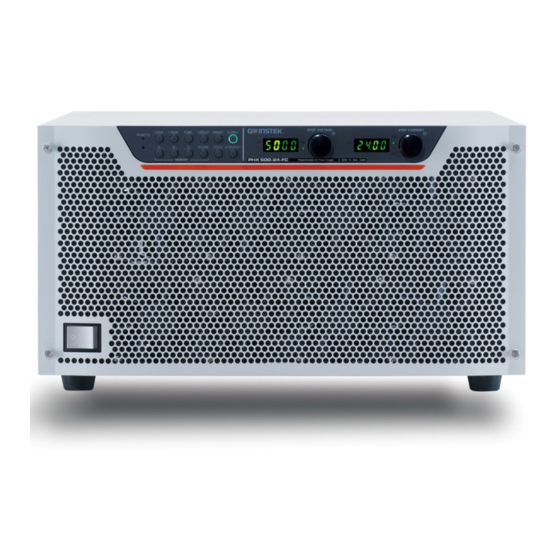
ABOUT THIS MACHINE Part Names and Functions Front Panel (12kW models shown) Front Panel Continued (6kW models shown) 10 11 12 13 . VOLTAGE . OUTPUT Voltage Setting/Selection Dial Output ON/OFF Toggle Key Selects the voltage, the OVP, and various other Toggles output ON/OFF. - Page 10 PHX-D Series . LOCK . ALARM RESET LOCK Key Alarm Reset Key Locks panel from use. Hold down for 1 second or more to cancel an alarm. Lights when Lock has been enabled. Below are the 3 types of Lock settings. They can be changed .
- Page 11 ABOUT THIS MACHINE Rear Panel (PHX 30-200, PHX 60-100) 24 25 26 27 Rear Panel (PHX 30-400) 24 25 26 27...
- Page 12 PHX-D Series Rear Panel (PHX 60-200) 24 25 26 27 Rear Panel (PHX 500-12) 24 25 26 27...
- Page 13 ABOUT THIS MACHINE Rear Panel (PHX 500-24) 24 25 Rear Panel (PHX 1000-6) 24 25 26 27...
- Page 14 PHX-D Series Rear Panel (PHX 1000-12) 24 25 26 27 . ISOLATED CONTROL . TERMINATION Insulation Control Connector Termination Resistor ON/OFF Switch This is the Status/Alarm Output Connector. When controlling one unit of this product via serial port, It is used for external analog control input of insulation please set the termination toggle switch to ON.
- Page 15 ABOUT THIS MACHINE DC Output Terminal. Terminal for Remote Sensing ! . Master/Booster Frame Ground (M/B FG) CAUTION FG terminal for parallel connection cable A Crimp-Style Terminal must be used. Please be This is the terminal for connecting the frame ground of !...
-
Page 16: Preparation And Connection
⑫ Insulation Control Connector (Attached to isolated control of power supply) --------------------- 1 item ⑬ External Control Connector (Attached to external control of power supply) (PHX 30-200, PHX 30-400, PHX 60-100, PHX 60-200, PHX 500-12, PHX 500-24) ------------ 1 item ⑭ Parallel Connection Terminal Cover (PHX 60-100, PHX 60-200, PHX 500-12, PHX 500-24, PHX 1000-6, PHX 1000-12) ---------- 1 package ⑮... -
Page 17: Placement
PREPARATION AND CONNECTION Placement To ensure proper and safe use of this product, please observe the following. ! WARNING Do not use in areas exposed to rain and water. Prohibited Do not place in areas in which flammable gases are present. Prohibited Do not insert any metallic pins, wires, screws, etc. -
Page 18: Connecting The Power Supply
PHX-D Series Connecting the Power Supply This product operates on a 342V to 440V and 45Hz to 65Hz three-phase AC power supply. To ensure proper and safe use of this product, please observe the following. ! DANGER ! Verify that the input power supply (power supply AC 342V to 440V) is turned off when wiring input terminals. -
Page 19: Connecting The Input Power Source
PREPARATION AND CONNECTION Connecting the Input Power Source ④ Insert other cables in the connector and fix ① Strip 10mm of the cable covering. the cables tightly in the same manner. 10mm ② Insert a cable in the hole of the ⑤Attach the cable to protective earth connector. - Page 20 PHX-D Series ⑥ Insert the input cables from step ④ into the ⑧ The picture shows tightening the lower screw. input terminal firmly. ⑦ Tighten the upper and lower screws and fix the ⑨ Bundle and fix the input cables with a inserted connector so that is does not fall off.
-
Page 21: Connecting Loads (Phx 30-200 And 60V Models)
PREPARATION AND CONNECTION Connecting Loads (PHX 30-200 and 60V Models) For wiring to the output terminal, please attach the M12 crimp-style terminal and be sure to tightly fasten the M12 bolts. MEMO Twisting wires can minimize the ripple and noise at the load terminal. - Page 22 PHX-D Series ! DANGER ! Verify that the main power supply for the power supply is turned off when connecting loads. Mandatory Do not wire loads when voltage is being outputted from the power supply. Prohibited ! CAUTION Use wires with sufficient cross section areas for load currents. !...
-
Page 23: Attaching The Output Terminal Cover
PREPARATION AND CONNECTION Attaching the Output Terminal Cover 1. Attach a supporter for attaching cover on one output terminal cover (both covers are identical in shape). *. Insert the supporter for attaching into the center part of the inside of the output terminal cover and fix it in place by screwing an M3x6mm from outside. - Page 24 PHX-D Series 4. Fasten the output terminal covers with an M3X6mm screw. 5. Attaching the output terminal cover is completed.
-
Page 25: Connecting Loads (Phx 30-400 Only)
PREPARATION AND CONNECTION Connecting Loads (PHX 30-400 only) For wiring to the output terminal, please attach the M12 crimp-style terminal and be sure to tightly fasten the M5 bolts. MEMO Twisting wires can minimize the ripple and noise at the load terminal. ... -
Page 26: Attaching The Output Terminal Cover
PHX-D Series ! DANGER ! Verify that the main power supply for the power supply is turned off when connecting loads. Mandatory Do not wire loads when voltage is being outputted from the power supply. Prohibited ! CAUTION Use wires with sufficient cross section areas for load currents. !... - Page 27 PREPARATION AND CONNECTION 2. The upper and lower output terminal cover can be checked from the front of the cover. Please refer to the following. 3. Snap the terminal covers together at the top and bottom along the groove on the terminal. 4.
-
Page 28: Connecting Loads (Phx 500V And 1000V Models)
PHX-D Series Connecting Loads (PHX 500V and 1000V Models) For wiring to the output terminal, please attach the M5 crimp-style terminal and be sure to tightly fasten the M5 screws. MEMO Twisting wires can minimize the ripple and noise at the load terminal. - Page 29 PREPARATION AND CONNECTION ! DANGER ! Verify that the main power supply for the power supply is turned off when connecting loads. Mandatory Do not wire loads when voltage is being outputted from the power supply. Prohibited ! CAUTION Use wires with sufficient cross section areas for load currents. !...
-
Page 30: Attaching The Output Terminal Cover
PHX-D Series Attaching the Output Terminal Cover 1. Attach a supporter for attaching cover on one output terminal cover (both covers are identical in shape). *. Insert the supporter for attaching into the center part of the inside of the output terminal cover and fix it in place by screwing an M3x6mm from outside. - Page 31 PREPARATION AND CONNECTION 4. Fasten the output terminal covers with an M3X6mm screw. 5. Attaching the output terminal cover is completed.
-
Page 32: Basic Usage
PHX-D Series ASIC USAGE Startup Display Once power is turned on (POWER switch pushed to ON), the output voltage will be displayed in the Number Display (voltage) and the model name and the total output capacity (in kW) will be displayed in the Number Display (current). -
Page 33: Default Settings
BASIC USAGE Default Settings Factory settings and settings after initialization are as follows: Settings Item (6kW Models) PHX 30-200 PHX 60-100 PHX 500-12 PHX 1000-6 Constant Voltage Set Value 0.00V 0.00V 0.0V Constant Current Set Value 210.0A 105.0A 12.60A 6.300A Over Voltage Protection 33.00V... - Page 34 PHX-D Series Operating as Constant Voltage Power Supply Please verify that the settings for Over Voltage Protection (OVP) circuit (page 49) and Over Current Protection (OCP) circuit (page 51) are in effect. MEMO Turn the POWER switch ON to startup the power supply. The voltage measurement value will be displayed in the When POWER is turned OFF for the top or Number Display (voltage) and the current measurement value...
- Page 35 BASIC USAGE Press the PRESET key to finalize settings. Confirms PRESET settings and returns to the measurement display mode. Press the OUTPUT key. Outputs with the set settings. The OUTPUT and CV lamps will light. MEMO While the PRESET lamp is lit, all other keys not mentioned in the above setting procedures cannot be used.
-
Page 36: Operating As Constant Current Power Supply36
PHX-D Series Operating as Constant Current Power Supply Please verify that the settings for Over Voltage Protection (OVP) circuit (page 49) and Over Current Protection (OCP) circuit (page 51) are in effect. Turn the POWER switch ON to startup the power supply. MEMO The voltage measurement value will be displayed in the When POWER is turned OFF for the top or... - Page 37 BASIC USAGE Press the PRESET key to finalize settings. Confirms PRESET settings and returns to the measurement display. Press the OUTPUT key. Outputs with the set settings. The "OUTPUT" and the “CC” lamp will light. MEMO While the " " lamp is lit, all other keys not PRESET mentioned in the above setting procedures cannot be used.
-
Page 38: Remote Sensing
PHX-D Series Remote Sensing Remote sensing is used for solving problems with voltage drop between the output terminal and load due to wiring by compensating for the voltage drop. Remote sensing is able to compensate voltages up to 5V per direction (one-way). -
Page 39: For Phx 30-200, 60-100 And Phx 60-200
BASIC USAGE For PHX 30-200, 60-100 and PHX 60-200: MEMO Remote C1: Electrolytic Capacitor 100 to 1000 μF Sensing (Low Impedance Item) Terminal C2: Film Capacitor 1 to 10 μF Connect when wishing to lower output ripple/noise from the load terminal. * When wiring, wiring materials Wiring should be twisted or be wired... -
Page 40: For Phx 500-12 And Phx 500-24
PHX-D Series For PHX 500-12 and PHX 500-24: MEMO C1: Electrolytic Capacitor 100 to 1000 μF (Low Impedance Item) C2: Film Capacitor 1 to 10 μF Remote Sensing Terminal Connect when wishing to lower output ripple/noise from the load terminal. M5 Screw +... -
Page 41: For Phx 1000-6 And Phx 1000-12
BASIC USAGE For PHX 1000-6 and PHX 1000-12: Remote Sensing Terminal ISOLATED CONTROL MEMO C1: Electrolytic Capacitor 100 to 1000 μF SENSIN (Low Impedance Item) C2: Film Capacitor 1 to 10 μF Connect when wishing to lower output ripple/noise from the load terminal. M5 Screw +... -
Page 42: Function Settings
PHX-D Series Function Settings This section covers setting parameters for various functions. Parameters that can be set are the device address, bitrate, parity, Output ON/OFF Toggle at external contact, selection of external analog control, OUTPUT settings when POWER is ON, voltmeter and ammeter display when OUTPUT is OFF, etc. For details, see the FUNCTION Settings Items List. -
Page 43: Settings Items List
7=CC Slew Rate PHX 30-200: 0.01V/s ~ 60.00V/s PHX 30-200: 60V/s PHX 30-400: 0.01V/s ~ 60.00V/s PHX 30-400: 60V/s PHX 60-100: 0.1V/s ~ 120.0V/s PHX 60-100: 120.0V/s PHX 60-200: 0.1V/s ~ 120.0V/s PHX 60-200: 120.0V/s CV Slew Rate Rising PHX 500-12: 1V/s~1000V/s... - Page 44 PHX-D Series Settings Items List (Continued) [FUNCTION Settings Items] Item Default Value Settings Item Parameters and their Ranges 0=Stop switching 0=Stop switching 1=Input Switch TRIP (Only for TRIP input and serious failures) Operation during Alarm 2=Input Switch TRIP (TRIP input, serious failures, OVP, and OCP) 0=Invalid 0=Invalid...
- Page 45 BASIC USAGE Settings Items List (Continued) [FUNCTION Settings Items] Item Settings Item Parameters and their Ranges Default Value Constant Voltage (CV) 0=Invalid 0=Invalid Insulation of external analog 1=Valid control signals * The insulation function is only available for the 1000V Constant Current (CC) 0=Invalid models.
- Page 46 Default Value PHX 30-200: 0 to 150mΩ 0Ω PHX 30-400: 0 to 75mΩ * This function can only be set PHX 60-100: 0 to 600mΩ for full-featured “F” type PHX 60-200: 0 to 300mΩ models. Internal Resistance Settings PHX 500-12: 0 to 41.7Ω...
- Page 47 BASIC USAGE Settings Items List (Continued) [FUNCTION Settings Items] Item Settings Item Parameters and their Ranges Default Value 2nd digit Internal Power Part (B) Power Monitoring Internal Power Part (A) Power Monitoring 1st digit Insulation Option Board Mounting Status HW FPGA Version Ex: 1.00 (Cannot be changed) Display only 1=ON...
-
Page 48: Setting Output On/Off Toggle Mode
PHX-D Series Setting Output ON/OFF Toggle Mode Output status at power supply is turned on (POWERON) can be changed. If this is set to 1 or 2 and the power supply is turned on (POWERON), output will begin even if the OUTPUT key is not pressed. -
Page 49: Useful Functions
USEFUL FUNCTIONS SEFUL FUNCTIONS Over Voltage Protection (OVP) In the event of an over voltage due to circuit failure of the power supply, improper use, load opens in constant current mode, etc. the output is turned OFF and switching is ceased to protect the load. The OVP voltage can be set to any value from 0.30V to 33.00V(PHX 30-200/400), 0.60V to 66.00V(PHX 60-100/200), 5.0V to 550.0V(PHX 500-12/24) or 10V to 1100V (PHX 1000-6/12). - Page 50 If the error code and OVP are not erased after holding down the ALARM RESET key, the power supply may be damaged. Turn power off immediately and contact your nearest GW Instek distributor or the GW Instek service center. MEMO ●...
-
Page 51: Over Current Protection (Ocp)
USEFUL FUNCTIONS Over Current Protection (OCP) In the event of an over current due to a short circuit in the load, the output is turned OFF and switching is ceased to protect the load. The OCP current can be set from 1% to 110% of the rated current. Setting/Canceling Over Current Protection Setting Over Current Protection Level . - Page 52 If the error code and OCP does not erase after holding down the OVP and OCP keys, the power supply may be damaged. Turn power off immediately and contact your nearest GW Instek distributor or the GW Instek service center. MEMO ● During serial data communication, recovery from alarm status is possible using commands.
-
Page 53: Setting Operation During Alarm
USEFUL FUNCTIONS Setting Operation during Alarm Setting can be done about whether input shutoff is done or switching stop (forced output OFF) is done for this machine at various types of alarm occurrence. Setting Procedures Press The Function “FUNC.” key. The FUNC. -
Page 54: Error Codes
Check slave unit display. malfunctioned. P_ERR E007 May have had a short May be damaged. interruption or voltage Contact the GW Instek Service Center. dip at the main power. Check whether slave unit’s power switch BST_NRDY E008 Slave unit's input voltage is abnormal. -
Page 55: Memory
USEFUL FUNCTIONS Memory Saves and loads the set values of the voltage, current, and various functions in memories “A”, “B”, and “C”. MEMO Settings Items that can be saved in memory are listed on page 56 “Panel Memory Savable Settings”. Caution If the number of parallel devices (total power) is changed, the saved content of the panel memory is initialized. -
Page 56: Panel Memory Savable Settings
PHX-D Series [Double-Action Loading] Set the parameter for FUNCTION settings item 54 to”1”. (See page 42 Function Settings on how.) Press the memory key you wish to load from. The voltage and current values stored in memory will blink in the Number Display. -
Page 57: Startup Mode Selection
Set Value 6 = Constant Current (CC) Priority Low Speed Mode MEMO The approximate time of high speed, medium speed, and low speed is as follows: Mode\ Model PHX 30-200/400 PHX 60-100/200 PHX 500-12/24 PHX 1000-6/12 CV High Speed 10ms... -
Page 58: Variable Slew Rate
① △V ② △t Range: 0.01V/s ~ 60.00V/s (PHX 30-200/400) 0.1V/s ~ 120.0V/s (PHX 60-100/200) Time (s)→ ①CV Slew Rate Rising 1V/s ~ 1000V/s (PHX 500-12/24) ②CV Slew Rate Falling 1V/s ~ 2000V/s (PHX 1000-6/12) △V... - Page 59 Assign the set value using the CURRENT dial. Range (Ex) 0.1A/s to 400.0A/s (PHX 30-200)(Resolution 0.1A/s) 0.1A/s to 800.0A/s (PHX 30-400)(Resolution 0.1A/s) 0.1A/s to 200.0A/s (PHX 60-100)(Resolution 0.1A/s) 0.1A/s to 400.0A/s (PHX 60-200)(Resolution 0.1A/s) 0.01A/s to 24.00A/s (PHX 500-12)(Resolution 0.01A/s) 0.01A/s to 48.00A/s (PHX 500-24)(Resolution 0.01A/s) 0.01A/s to 12.00A/s (PHX 1000-6)(Resolution 0.01A/s)
-
Page 60: Sequential On/Off
PHX-D Series Sequential ON/OFF * This function can only be set for full-featured “F” type models. Toggles the Output ON/OFF for multiple PHX Series power supplies simultaneously or using time delays. Optional cables (PHX-003) are required for connection. (Optional) Sequential ON/OFF Connection Sequential Master #1 シーケンシャルマスター #1... - Page 61 USEFUL FUNCTIONS Using the Sequential Function MEMO Output is turned ON/OFF after delay time (tdon, For sequential master machines, delay time tdoff) that are set for each machine triggered by (tdon, tdoff) can also be set. OUTPUTON signal of the sequential master. Sequential Master PHX #1(+5V) td1 on...
- Page 62 PHX-D Series Set the Sequential Master and Sequential Slave Unit Settings Select Item number 60 with the VOLTAGE dial and set the Master and Slave settings with the CURRENT dial. Set the Master to the address "1". Set the Slave to a setting other than the address "1". * If there are more than one slaves, set the addresses avoiding address duplication.
-
Page 63: Key Lock
USEFUL FUNCTIONS Key Lock Use the LOCK key when protecting settings from careless operations is desired. Key Lock Settings Pressing the LOCK key will restrict key inputs. LOCK lamp will light. The status of the Lock Key can be selected under the FUNCTION Settings Item Number 53 parameters from the following 3 types below. -
Page 64: Variable Internal Resistance
Range PHX 30-200: 0Ω to 150mΩ (Resolution: 2mΩ) PHX 30-400: 0.0Ω to 75.0mΩ (Resolution: 1mΩ) PHX 60-100: 0Ω to 600mΩ (Resolution: 5mΩ) PHX 60-200: 0Ω to 300mΩ (Resolution: 2mΩ) PHX 500-12: 0Ω to 41.7Ω (Resolution: 0.5Ω) PHX 500-24: 0Ω to 20.8Ω (Resolution: 0.5Ω) PHX 1000-6: 0Ω... -
Page 65: Measurement Display Smoothing
USEFUL FUNCTIONS Press the FUNC. key again to finish. Confirms settings and returns the Number Display to measurement display mode. MEMO It is possible to continue to change other setting items without pressing the “FUNC.” key. In this case, press the “FUNC.” key to confirm settings once changes are complete. -
Page 66: Linearity Compensation
PHX-D Series Linearity Compensation This function provides a high output setting accuracy by measuring and compensating the nonlinearity of the output caused by feedback systems or DA converters/Error Amplifiers used as a DC power supply voltage or current reference value. This is normally used when the compensation function is turned ON (Parameter 1 or 2). -
Page 67: Setting Beep Sound
USEFUL FUNCTIONS Setting Beep Sound This machine emits a beep sound when a button is pressed or an alarm occurs. You can set whether beep sounds are emitted or not. Setting Procedures Press The Function “FUNC.” key. The FUNC. lamp will light. The Setting Item Number will be displayed in the Number Display (voltage) and the parameter will be displayed in the Number Display (current). -
Page 68: Using In Digital Data Communication
Besides, remote control of more than one units using one communication terminal can be realized by multi-connecting a Serial I/F 2 connector. Command forms can be selected from 2 types; command forms in conformance with IEEE488.2 Common Command and SCPI Protocol, or forms in conformance with GW Instek PHX Series Commands. -
Page 69: Multiple Connections
USING IN DIGITAL DATA COMMUNICATION External Control Connector SERIAL I/F 2 Connector Types (RS-485 compliant ) Pin No. Name IN/OUT Pin No. Name IN/OUT SERIAL I/F 2 Power supply side: RJ-45 (Female) External Control Connector "SERIAL I/F 2" Pin Placement Multiple Connections The diagram below shows the connections for controlling multiple PHX Series power supplies with one communication terminal including a computer or a sequencer. -
Page 70: Serial Port Settings
PHX-D Series #1 [ON] ON OFF PHX-004 computer #2 [OFF] ON OFF #n [ON] ON OFF Controlling PHX Series power supplies on multiple channels via computer Serial Port Settings Below are the serial port settings for PHX Series power supplies. Serial Port Settings Item Set Value Ranges... -
Page 71: Command Send Interval
USING IN DIGITAL DATA COMMUNICATION Command Send Interval When sending commands continuously to the PHX power supply due to there being no flow control function, a delay is required on the communication terminal side. If receiving has failed, the PHX Series power supply will return an alarm response. Alarm response: PHX standard commands: "ERROR"... -
Page 72: Accessing
PHX-D Series Accessing Access Procedure For controlling via communication commands, match the address assigned by the "Device Address Assign" command with the device address, set under FUNCTION Settings Item 60 "Device Address". At this point, the front panel "REMOTE" LED will light and control via communication commands will be granted. -
Page 73: Communication With Multiple Connections
USING IN DIGITAL DATA COMMUNICATION Communication with Multiple Connections Below are Remote Control examples when connected to two PHX Series power supplies. Connection Configuration Device Address: 1 Note: If RS-485 control, set to other than "1" RS-232C/RS-485 PHX-003 Device Address: 2 ... -
Page 74: Communication Commands
Command forms can be selected from 2 types; PHX standard command forms in conformance with IEEE488.2 Common Command and SCPI Protocol, or PHX command compatible forms in conformance with GW Instek PHX Series Commands. Command forms can be selected under FUNCTION Settings Item 63 "Command Forms". - Page 75 USING IN DIGITAL DATA COMMUNICATION Upper and Lower-Case Sensitive Common Commands and SCPI Commands are not case-sensitive. <Ex.> OUTPUT Output Outp OUTP OUTPut Short Form & Long Form SCPI Command has two forms; abbreviated (Short) and normal (Long) form. Command words must use either of the two forms.
- Page 76 PHX-D Series Further, when using semi-colons, if there are commands of the same command level, the root command can be omitted. <Ex.> Due to there being a command within the same level, everything after CONTain is executed. ALM:CLEar;CONTain:CC <NRf> When a colon " : " is detected in the program message, the command level is moved to the next level. If a colon "...
-
Page 77: Phx Standard Command Details
USING IN DIGITAL DATA COMMUNICATION PHX Standard Command Details IEEE488.2 Common Command This section explains about the commands which conform to IEEE488.2 Common Command. Common Command List Command Command Name Summary Type *IDN Requests device information QUERY Only *RST Resets set parameters SET Only *IDN : Identification Query... -
Page 78: Scpi Command
PHX-D Series SCPI Command This section explains about commands which conform to SCPI Protocol. ADDRess Level ADDRess level command is used only for assigning the device address. Command Name Summary Command Type ADDRess Assigning Device Address SET Only ADDRess : Assigns Device Address Function: Assigns the device address for PHX power supplies. -
Page 79: Alm Level
USING IN DIGITAL DATA COMMUNICATION ALM Level ALM level command corresponds to external output settings for alarm reset and status information. Command Command Name Summary Type :CLEar Executes alarm reset SET Only :CONTain Sets whether to include CC_STS in LEVEL1_ALM or not Both Sets whether to include CV_STS in LEVEL1_ALM or not Both... - Page 80 PHX-D Series ALM:CONTain:CV :Sets whether to contain CV_STS in LEVEL1_ALM Function: Sets whether to contain CV_STS status in LEVEL1_ALM output condition. Same as FUNCTION Settings Item 74 Format: ALM:CONTain:CV <NRf> Type: SET command, QUERY command Parameters: 0: Does not include in LEVEL1_ALM 1: Includes in LEVEL1_ALM Response: 0, 1...
-
Page 81: Output Level
USING IN DIGITAL DATA COMMUNICATION OUTPut Level OUTPut level command corresponds to functions concerning output control. Command Command Name Summary Type OUTPut :DELay Sets Output ON Delay Time Both :OFF Sets Output OFF Delay Time Both :EXTernal :MODE Sets operation mode for output control at External Both Contact :HOT... - Page 82 PHX-D Series OUTPut:EXTernal:MODE :Sets operation mode for Output Control at External Contact Points Function: Sets operation mode for Output Control at External Contact Points Same as FUNCTION Settings Item 10 Format: OUTPut:EXTernal:MODE <NRf> Type: SET command, QUERY command Parameters: 0: Invalid 1: When close Output is ON, When open Output is OFF 2: When close normal operation, When open Output is OFF Response:...
- Page 83 USING IN DIGITAL DATA COMMUNICATION OUTPut:MODE :Sets Startup Mode Function: Sets the Output Startup Mode Same as FUNCTION Settings Item 1 Format: OUTPut:MODE <NRf> Type: SET command, QUERY command Parameters: 0=CV Priority, (High Speed) 1=CV Priority (Medium Speed) 2=CV Priority (Low Speed) 3=CV Slew Rate 4=CC Priority (High Speed) 5=CC Priority (Medium Speed)
-
Page 84: Measure Level
PHX-D Series MEASure Level MEASure level command corresponds to functions concerning measurement, such as retrieving voltage and current measurements. Command Name Summary Command Type MEASure :CORRection :MODE Sets operation mode for the Linear Compensation Both Function :MVAV Sets Moving Average process for measurement values Both [:SCALar] :CURRent... - Page 85 USING IN DIGITAL DATA COMMUNICATION MEASure:MVAV :Sets Moving Average process for Measurement Values Function: Sets the Moving Average process for Measurement Values Same as FUNCTION Settings Item 11 Format: MEASure:MVAV <NRf> Type: SET command, QUERY command Parameters: 0: Moving Average for measured value is not processed 1: Moving Average for measured value is processed Response: Same as parameters...
- Page 86 PHX-D Series MEASure[:SCALar]:POWer[:DC] :Retrieves Power Measurement Values Function: Retrieves electric power measurement values Format: MEASure[:SCALar]:POWer[:DC]? Type: QUERY command only Response: Returns same resolution data as the power meter Restrictions: Alarm response is returned for normal SET commands in the following conditions ·...
-
Page 87: Source Level
USING IN DIGITAL DATA COMMUNICATION SOURce Level SOURce level command corresponds to functions concerning output settings, such as settings for voltage and current values. Command Name Summary Command Type [SOURce] :CURRent [:LEVel] [:IMMediate] [:AMPLitude] Sets Output Current Both :PROTection [:LEVel] Sets OCP Current Both :SLEW... - Page 88 PHX-D Series [SOURce]:CURRent[:LEVel][:IMMediate][:AMPLitude] : Sets Output Current Function: Sets the output current Format: [SOURce]:CURRent[:LEVel][:IMMediate][:AMPLitude] <NRf> Type: SET command, QUERY command Parameters: Range varies depending on the total output capacity of the parallel connection. Response: Same as parameters Output Current Range Model (Type) PHX 30V Rated PHX 60V Rated...
- Page 89 USING IN DIGITAL DATA COMMUNICATION [SOURce]:CURRent:PROTection[:LEVel] :Sets OCP Current Function: Sets the over current (OCP). Format: [SOURce]:CURRent:PROTection[:LEVel] <NRf> Type: SET command, QUERY command Parameters: Range varies depending on the total output capacity of the parallel connection. Response: Same as parameters OCP Range Model (Type) PHX 30V OCP...
- Page 90 PHX-D Series [SOURce]:CURRent:SLEW:RISing : Sets the CC Slew Rate Rising Function: Sets the CC slew rate for rising. Same as FUNCTION Settings Item 4 Format: [SOURce]:CURRent:SLEW:RISing <NRf> Type: SET command, QUERY command Parameters: Range varies depending on the total output capacity of the parallel connection. Response: Same as parameters CC Slew Rate Range...
- Page 91 USING IN DIGITAL DATA COMMUNICATION [SOURce]:CURRent:SLEW:FALLing : Sets CC Slew Rate Falling Function: Sets the CC slew rate for falling. Same as FUNCTION Settings Item 5 Format: [SOURce]:CURRent:SLEW:FALLing <NRf> Type: SET command, QUERY command Parameters: Range varies depending on the total output capacity of the parallel connection. See CC Slew Rate Ranges for range settings.
- Page 92 PHX-D Series [SOURce]:MEMory:RECall:MODE : Sets Load Order for Panel Memory Function: Sets the order of loading for panel memory(A/B/C) Same as FUNCTION Settings Item 54 Format: [SOURce]:MEMory:RECall:MODE <NRf> Type: SET command, QUERY command Parameters: 0: Determines by Single-Action 1: Determines by Double-Action Response: Same as parameters Restrictions:...
- Page 93 USING IN DIGITAL DATA COMMUNICATION [SOURce]:RESistance[:LEVel][:IMMediate][:AMPLitude] : Sets internal resistance Function: Sets the internal resistance Format: [SOURce]:RESistance[:LEVel][:IMMediate][:AMPLitude] <NRf> Type: SET command, QUERY command Parameters: Range varies on the model and the number of parallel connected devices Response: Same as parameters Model (Type) PHX 30V PHX 60V...
- Page 94 Format: [SOURce]:VOLTage[:LEVel][:IMMediate][:AMPLitude] <NRf> Type: SET command, QUERY command Parameter: PHX 30-200/400: 0.00V to 31.50V, PHX 60-100/200: 0.00V to 63.00V, PHX 500-12/24: 0.0V to 525.0V, PHX 1000-6/12: 0V to 1050V. Response: Same as parameters Restrictions: Alarm response is returned for normal SET commands in the following conditions ·...
-
Page 95: Status Level
Format: [SOURce]:VOLTage:SLEW:RISing <NRf> Type: SET command, QUERY command Parameter: PHX 30-200/400: 0.01V/s to 60.00V/s, PHX 60-100/200: 0.1V/s to 120.0V/s, PHX 500-12/24: 1V/s to 1000V/s, PHX 1000-6/12: 1V/s to 2000V/s Response: Same as parameters Restrictions: Alarm response is returned for normal SET commands in the following conditions ·... - Page 96 PHX-D Series STATus:MEASure:CONDition : Retrieves Power Supply Status Function: Retrieves the status of the power supply Format: STATus:MEASure:CONDition? Type: QUERY command only Response: 3 byte 16-base data Power Supply Bit List Status Name Summary Internal power unit (D) P-ON P-ON(D)_STS status Power unit power-on Power unit power-off...
-
Page 97: System Level
USING IN DIGITAL DATA COMMUNICATION SYSTem Level SYSTem level command corresponds to the settings of main FUNCTION items. Command Command Name Summary Type SYSTem :COMMunicate :SERial [:RECeive] :BAUD Sets Bitrate Both :PACE Sets Acknowledge Response Both :PARity [:TYPE] Sets Parity Both :UNIT Sets Query Response Unit Load... - Page 98 PHX-D Series SYSTem:COMMunicate:SERial[:RECeive]:BAUD : Sets Bitrate Function: Sets the bitrate Same as FUNCTION Settings Item 61 Format: SYSTem:COMMunicate:SERial[:RECeive]:BAUD <NRf> Type: SET command, QUERY command Parameters: 0: 2400bps 1: 9600bps 2: 19200bps 3: 38400bps Response: 2400, 9600, 19200, 38400 Restrictions: Alarm response is returned for normal SET commands in the following conditions - While operating as a series operation slave unit - While operating as a parallel operation slave unit !...
- Page 99 USING IN DIGITAL DATA COMMUNICATION SYSTem:COMMunicate:SERial[:RECeive]:PARity[:TYPE] : Sets the parity Function: Sets the parity Same as FUNCTION Settings Item 62 Format: SYSTem:COMMunicate:SERial[:RECeive]:PARity[:TYPE] <String> Type: SET command, QUERY command Parameters: ODD: Odd number EVEN: Even number NONE: None Response: ODD, EVEN, NONE Restrictions: Alarm response is returned for normal SET commands in the following conditions - While operating as a series operation slave unit - While operating as a parallel operation slave unit...
- Page 100 PHX-D Series SYSTem:CONTrol:CURRent:MODE : Sets Mode for Current Setting Control Method Function: Sets mode for the method on setting the current Same as FUNCTION Settings Item 71 Format: SYSTem:CONTrol:CURRent:MODE <NRf> Type: SET command, QUERY command Parameters: 0: Front Panel, Digital Communication 1: External Voltage 2: External Resistance Type-A 3: External Resistance Type-B...
- Page 101 USING IN DIGITAL DATA COMMUNICATION SYSTem:CONTrol:VOLTage:MODE : Sets Mode for Voltage Setting Control Method Function: Sets mode for the method on setting the voltage Same as FUNCTION Settings Item 70 Format: SYSTem:CONTrol:VOLTage:MODE <NRf> Type: SET command, QUERY command Parameters: 0: Front Panel, Digital Communication 1: External Voltage 2: External Resistance Type-A 3: External Resistance Type-B...
- Page 102 PHX-D Series SYSTem:ERRor :Reads Error Message Function: After an error response is received, send this command to retrieve the cause for the generated error Format: SYSTem:ERRor? Type: QUERY command only Response: Error Code, Error Message Table-Error Codes & Error Messages Error Code Error Messages Meaning...
- Page 103 USING IN DIGITAL DATA COMMUNICATION SYSTem:KEYLock:MODE : Sets LOCK Mode Function: Sets the mode for the Key Lock on the front panel Same as FUNCTION Settings Item 53 Format: SYSTem:KEYLock:MODE <NRf> Type: SET command, QUERY command Parameters: 0: Only LOCK key is usable 1: Only OUTPUT and LOCK keys are usable 2: VOLT/CURR dials are non-usable (Along with this, PRESET key, FUNC key, OVP key, and OCP key are also non-usable)
- Page 104 PHX-D Series SYSTem:PRESet:MODE : Sets Method to Determine PRESET Contents Functions: Sets the method in which the PRESET contents are determined Same as FUNCTION Settings Item 50 Format: SYSTem:PRESet:MODE <NRf> Type: SET command, QUERY command Parameters: 0: Changes set values after PRESET mode is completed 1: Changes set values while PRESET mode is operating Response: Same as parameters...
- Page 105 USING IN DIGITAL DATA COMMUNICATION SYSTem:TRIP : Executes TRIP Function: Executes TRIP operation (output stop) by setting operation for stopping output Format: SYSTem:TRIP Type: SET command only Parameters: None <Ex.> SYST:TRIP SYSTem:TRIP:MODE : Sets operation for stopping output during TRIP execution or serious/light failure Function: Sets operation for stopping output during TRIP execution or serious/light failure Same settings as FUNCTION Settings Item 9...
- Page 106 PHX-D Series SYSTem:BUZzer:ALArm : Sets ON/OFF of alarm sound at alarm occurrence Function: Sets ON/OFF of alarm sound at alarm occurrence Same as FUNCTION Settings Item 91 Format: SYSTem:BUZzer:ALArm <NRf> Type: SET command, QUERY command Parameters: 0: OFF 1: ON Response: Same as parameters Restrictions: None...
-
Page 107: Phx Compatible Commands
USING IN DIGITAL DATA COMMUNICATION PHX Compatible Commands PHX compatible commands are commands which conform to GW Instek PHX Series communication command format. Remote control is possible only for common functions between PHX series. PHX commands are listed below. For details on each command, see the pages listed below. -
Page 108: Phx-Compatible Command Format
PHX-D Series PHX-compatible Command Format All commands and responses are ASCII character strings. Characters "A" to "Z" are recognized as command strings and characters "+", "-", ".", and "0" to"9" are recognized as parameters. PHX-compatible Command Group Sending Multiple commands can be sent in a single string by separating commands with ",". <Ex.>A1,MV10.00,MC2.00,OT1 However, a single string with multiple commands assigning addresses will error. -
Page 109: Phx-Compatible Command Details
USING IN DIGITAL DATA COMMUNICATION PHX-compatible Command Details This section explains the SET commands of PHX based commands. :Assigns Device Address Function: Assigns the device address for PHX power supplies. Format: *: Set value within range Range: 0~50 Assigned Address 0 is a global address. Assign addresses to all multi-connected PHX Series power supplies. - Page 110 Sets the OVP voltage Format: *: Set value within range Range: 0.30 to 33.00 (PHX 30-200/400), 0.60 to 66.00 (PHX 60-100/200), 5.0 to 550.0 (PHX 500-12/24), 10 to 1100 (PHX 1000-6/12) Values other than ranges will result in parameter errors. <Ex.>...
- Page 111 <Ex.> A1,MC12.00 : Sets Output Voltage Function: Sets the output voltage Format: *: Set value within range Range: 0.00 to 31.50 (PHX 30-200/400), 0.00 to 63.00 (PHX 60-100/200), 0.0 to 525.0 (PHX 500-12/24), 0 to 1050 (PHX 1000-6/12) <Ex.> A1,MV500.0...
-
Page 112: Phx-Compatible Read-Back Commands
PHX-D Series : Sets Output ON/OFF Function: Sets the output ON/OFF Format: *: Set value Set Value: 0: OUTPUT "OFF" 1: OUTPUT "ON" Values other than 0 and 1 result in parameter errors. <Ex.> A1,OT0 : Executes Breaker Trip Function: Executes breaker trip Format: *: Set values... - Page 113 USING IN DIGITAL DATA COMMUNICATION : Read-Back Measurement Data (Voltage/Current) Function: Retrieves measured voltage/current values from the PHX power supply with the specified device address Format: Read-Back Format: A*1,*2V,*3A *1~*2:Read-Back value Read-Back Value: *1: Device address of the responded PHX power supply *2:Output Voltage Set Value (Max.
- Page 114 PHX-D Series <Ex.> A1,TK3 A1,STAT1000001 : Read-Back Measured Voltage Data Function: Retrieves the measured voltage data from the PHX power supply with the specified device address Format: Read-Back Format: *: Read-Back Value *: Specified PHX power supply’s output voltage measurement value (Max. no. of decimal Read-Back Value: places is 2) <Ex.>...
-
Page 115: Using In Series/Parallel Operation115
! CAUTION Parallel operation is only possible with the same-voltage PHX series models. (Ex: Parallel operation of PHX 60-100 and PHX 60-200 is possible.) FUNCTION items for when operating in Slave cannot be set by only references. ... -
Page 116: Connection
PHX-D Series Connection Connect as shown in the below diagram. Connect from the first unit’s (Master) M/B CONTROL Connector OUT to the second unit’s (Slave) M/B CONTROL Connector IN. Connect from the second unit’s M/B CONTROL Connector OUT to the third unit (Slave). -
Page 117: Error Codes
USING IN SERIES/PARALLEL OPERATION 5. The voltage measurement is displayed on the Number Display (voltage) of the master, and the current measurement is displayed on the Number Display (current) of the master. Total current value is displayed in the bottom Number Display. Select power display with the "Display"... -
Page 118: Series Operation (Excluding Phx 1000-6/12)118
The indication on the front display during series operation shows the outputs of the Master unit and the Slave unit respectively. (When the output voltage is 1000V(PHX 500-12/24)/120V(PHX 60-100/200)/60V(PHX 30-200/400), both the Master unit and the Slave unit will be 500.0V(PHX 500-12/24)/60.00V(PHX 60-100/200) /30.00V(PHX 30-200/400.) Series operation is not supported on the PHX 1000-6/12. -
Page 119: Connection
USING IN SERIES/PARALLEL OPERATION Connection Connect as shown in the diagram below. (Slave Unit) Twisted Cable (Master Unit) Load Twisted Cable Series Control Connector 絶縁 Insulation Control Connector External Control Connector... -
Page 120: Operation
PHX-D Series Load Wire Connection Connect wires from the Slave’s minus terminal to the Master’s plus terminal. Connect wires from the Slave’s plus terminal to the Load’s plus terminal. Connect wires from the Master’s minus terminal to the Load’s minus terminal. Control Terminal Wiring ... - Page 121 60-100/200, PHX 30-200/400) and the constant offset calibration value of output voltage setting. current setting value to 0.1A(PHX 500-12/24)/1.0A(PHX 60-100/200, PHX 30-200/400) and set the output to ON. On how to set, see Operating as Constant Voltage Power Supply under Basic Operations.
- Page 122 PHX-D Series Press the FUNC. key of the Slave. Turn the VOLTAGE dial of the Slave unit to display the setting item number 38 in the Number Display (voltage). * At that time, turn off the Number Display (current). 10. Adjust the CURRENT dial of the Slave so that the display of the Slave unit’s digital multimeter for output voltage measurement is the same as the display of the Master unit’s digital multimeter for...
-
Page 123: Controlling With External Analog & Contact Signals
CONTROLLING WITH EXTERNAL ANALOG & CONTACT SIGNALS ONTROLLING WITH EXTERNAL ANALOG & CONTACT SIGNALS Using External Control Terminals This section covers proper methods when operating the PHX Series Power Supply externally. On the rear panel of this power supply, there are the connector for external control (30V, 60V and 500V models only) and the connector for insulation control(only 1000V models can use isolated control), which can be applied and used for various purposes combined with the FUNCTION items. - Page 124 PHX-D Series Series Control Connector Insulation Control Lock Lever External Control Connector Connector Maker : Phoenix Contact Maker : Phoenix Contact Type : MC1.5/16-STF-3.81 Type : DFMC1,5/13ST3,5LR Cat.No.: 1827842 Cat.No.: 1790593 MEMO MEMO How to insert wire into insulation control connector How to insert wire into external control connector Push in a flat-head screwdriver to the lever of the hole upper of Turn the screw at the upper part of the connector clockwise using...
-
Page 125: External Control Connector Terminal List (30V, 60V , 500V Models Only)
CONTROLLING WITH EXTERNAL ANALOG & CONTACT SIGNALS External Control Connector Terminal List (30V, 60V , 500V models only) Terminal Terminal Signal Name Signal Name Voltage Monitoring Output Common for Analog Signal Current Monitoring Output Common for Analog Signal Output Voltage Control, External Voltage Input Common for Analog Signal Output Voltage Control, External Resistance Output Voltage Control, External Resistance... -
Page 126: Toggling Output On/Off With External Contacts
PHX-D Series Toggling Output ON/OFF with External Contacts * This function is only applicable to 30V, 60V and 500V models. The output for PHX power supplies can be toggled ON/OFF using outputs from small capacity contact or photocoupler. Use a photocoupler or a small signal relay or switch with a minimum contact capacity of 5V, 2.5mA. !... - Page 127 CONTROLLING WITH EXTERNAL ANALOG & CONTACT SIGNALS Setting Procedures Press the Function "FUNC." key. The FUNC. lamp will light. The Setting Item Number will be displayed in the Number Display (voltage) and the parameter will be displayed in the Number Display (current). Select Item number 10 with the VOLTAGE dial.
-
Page 128: Toggling Output On/Off With Insulation External Contacts
PHX-D Series Toggling Output ON/OFF with Insulation External Contacts * This function can only be set for the models with the insulation option (1000V models). The output for PHX 1000-6/12 Series power supplies can be toggled ON/OFF using outputs from small capacity contact or photocoupler. - Page 129 CONTROLLING WITH EXTERNAL ANALOG & CONTACT SIGNALS Setting Procedures Press the Function "FUNC." key. The FUNC. lamp will light. The Setting Item Number will be displayed in the Number Display (voltage) and the parameter will be displayed in the Number Display (current). Select Item number 10 with the VOLTAGE dial.
-
Page 130: Trip Operation With External Contacts
PHX-D Series TRIP Operation with External Contacts * This function is only applicable to 30V, 60V and 500V models. The input for this machine can be shut off (switching stop by setting) using output from small capacity contacts or photocouplers. Use a photocoupler or a small signal relay or switch with a minimum contact capacity of 5V, 2.5mA. -
Page 131: Trip Operation With Insulation External Contacts
CONTROLLING WITH EXTERNAL ANALOG & CONTACT SIGNALS TRIP Operation with Insulation External Contacts * This function can only be set for the models with the insulation option (1000V models). The input for this machine can be shut off (switching stop by setting) using output from small capacity contacts or photocouplers. -
Page 132: Output Voltage Control
PHX-D Series Output Voltage Control Output Voltage Control with External Resistance * This function is only applicable to 30V, 60V and 500V models. 1. Output Voltage Control with External Resistance (A) This section describes how to set the output voltage zero when the external resistance value is infinity. - Page 133 CONTROLLING WITH EXTERNAL ANALOG & CONTACT SIGNALS Setting Procedures Press the Function "FUNC." key. The FUNC. lamp will light. The Setting Item Number will be displayed in the Number Display (voltage) and the parameter will be displayed in the Number Display (current). Select Item number 70 with the VOLTAGE dial.
- Page 134 PHX-D Series 2. Output Voltage Control with External Resistance (B) This section describes how to set the output voltage to zero when the external resistance value is zero (short). The output voltage is derived from the following formula. Output Voltage [V] kΩ...
-
Page 135: Resistance (B)
CONTROLLING WITH EXTERNAL ANALOG & CONTACT SIGNALS 3. Output Voltage Control with External Resistance (C) This section describes how to set the output voltage zero when the external resistance value is 10kΩ. The output voltage is derived from the following formula. Output Voltage [V] = ... - Page 136 * This function is only applicable to 30V, 60V and 500V models. Output voltage is proportionate to the external DC voltage. Outputs from 0 to a rated output voltage of 500V(PHX 500-12/24)/60V(PHX 60-100/200)/30V(PHX 30-200/400) for external voltages 0 to 10V. The external voltage uses what can produce a 1mA current.
-
Page 137: Output Voltage Control With Insulation External Voltage
CONTROLLING WITH EXTERNAL ANALOG & CONTACT SIGNALS Output Voltage Control with Insulation External Voltage * This function can only be set for the models with the insulation option (1000V models). Output voltage is proportionate to the external DC voltage. The external voltage is insulated from output of this machine. Outputs from 0 to a rated output voltage of 1000V(PHX 1000-6/12) for external voltages 0 to 10V. -
Page 138: Output Current Control
PHX-D Series Output Current Control Output Current Control via External Resistance * This function is only applicable to 30V, 60V and 500V models. 1. Output Current Control via External Resistance (A) This section describes how to set the output current zero, when the external resistance value is infinite (open). - Page 139 CONTROLLING WITH EXTERNAL ANALOG & CONTACT SIGNALS Setting Procedures Press the Function "FUNC." key. The FUNC. lamp will light. The Setting Item Number will be displayed in the Number Display (voltage) and the parameter will be displayed in the Number Display (current). Select Item number 71 with the VOLTAGE dial.
-
Page 140: Output Current Control Via External Resistance(B)
PHX-D Series 2. Output Current Control via External Resistance(B) This section describes how to set the output current to zero when the external resistance value is zero (short). The output current is derived from the following formula. Output Current [A] kΩ... -
Page 141: Output Current Control Via External Resistance(C)
CONTROLLING WITH EXTERNAL ANALOG & CONTACT SIGNALS 3. Output Current Control via External Resistance(C) This section describes how to set the output current zero when the external resistance value is 10kΩ. The output current is derived from the following formula. Output Current [A] ... -
Page 142: Output Current Control Via External Voltage
PHX-D Series Output Current Control via External Voltage * This function is only applicable to 30V, 60V and 500V models. Outputs current, which is proportionate to the direct current voltage added from external voltage. Outputs from 0 to the maximum output current of 100A(PHX 60-100), 200A(PHX 60-200,PHX 30-200), 12A(PHX 500-12), 24A(PHX 500-24) or 400A(PHX 30-400) for external voltage of 0 to 10V. -
Page 143: Output Current Control With Insulation External Voltage
CONTROLLING WITH EXTERNAL ANALOG & CONTACT SIGNALS Setting Procedures Set the parameter to 1 (External Voltage) according to the procedure on page 139. Output Current Control with Insulation External Voltage * This function can only be set for the models with the insulation option (1000V models). -
Page 144: Analog Output Monitor
PHX-D Series Analog Output Monitor * This function is only applicable to 30V, 60V and 500V models. This can produce the DC voltage, which is proportional to the output voltage and output current. Use when wishing to surveillance the output with an external meter or recorder. Outputs a "0~10V"... -
Page 145: Insulation Analog Output Monitor
CONTROLLING WITH EXTERNAL ANALOG & CONTACT SIGNALS Insulation Analog Output Monitor * This function can only be set for the models with the insulation option (1000V models). This can produce the DC voltage, which is proportional to the output voltage and output current and is insulated from the output terminal. -
Page 146: Status Output
PHX-D Series Status Output This can externally output the operational status of the PHK Series power supply. Which is attached to the Output Circuit Isolated Control of the Output is given by an open collector insulated by a photocoupler. main body. Insulation Control Connector LEVEL1_ALM LEVEL2_ALM... -
Page 147: Level_Alm1 Settings
CONTROLLING WITH EXTERNAL ANALOG & CONTACT SIGNALS LEVEL_ALM1 Settings This handles the operation mode’s status signal as a LEVEL1_ALM (alarm status). It can also be used for surveillance as an alarm when switching from constant voltage to constant current. Status Signals that can be set in LEVEL1_ALM CV_STS (Constant Voltage Operation) CC_STS (Constant Current Operation) Setting Procedures... -
Page 148: Special Loads
PHX-D Series PECIAL LOADS This section explains about loads with reverse current and pulse current loads as special loads. Loads with Reverse Current ! CAUTION This machine does not have functions to stabilize the output voltage against reverse current from loads. If the maximum sink current is exceeded, the output voltage will rise above the rated value and burn-out the internal circuits. -
Page 149: Pulse Current Loads
* In the case of 125mA ± 20%(PHX 1000-6) / 250mA ± 20%(PHX 500-12, PHX 1000-12) / 500mA ± 20%(PHX 500-24) / 1A ± 20%(PHX 60-100, PHX 30-200) / 2A ± 20%(PHX 60-200, PHX 30-400) parallel connection, the sink (absorb) current of the PHX power supplies is the total of the sink current of parallel connected units. - Page 150 PHX-D Series ! CAUTION • If sensing is done with the secondary battery connected and the reverse current blocking diode equipped, a potential difference occurs between each output and the sensing terminal because the secondary battery becomes the source of voltage at power supply's output OFF.
-
Page 151: Maintenance
At your request maintenance services will be provided. However, this will impose a fee. When you need repair and maintenance services, please contact the sales distributor from that you purchased the product or make requests using the maintenance service from in GW Instek's homepage. Requests When making repair requests, please include the device's product number (12 digit number at the rear panel of product) and the firmware version. -
Page 152: Periodical Check And Replacement Of Air Filter
PHX-D Series Periodical Check and Replacement of Air Filter The air filter is attached inside of the front panel. Please perform pericdical cleaning and replacement of the filter before the clogging becomes severe. ! CAUTION Deterioration in a cooling effect due to the clogging of the air filter may cause fault. Therefore, please perform the periodical cleaning and replacement. - Page 153 MAINTENANCE Attach the air filter. Please fix the filter preventing lateral and vertical movement by holding with the protuberances (three parts) on the back of the front cover. The air filter has directionality. Set the air filter so that the positioning parts are placed in the upper side. After that arrange shorter side from the edge of the filter on the right side and longer side from the edge of the filter on the left side.
-
Page 154: Calibration
PHX 1000-12 Display Accuracy : 0.005% or more 30A/50mV 0.1% PHX 500-24 (Equipped with a measuring range from 1mV 200A/50mV 0.1% 100A PHX 60-100 to 100V(30V and 60V models) or 1000V(500V 300A/50mV 0.1% 200A PHX 60-200 and 1000V models.) 300A/50mV 0.1%... - Page 155 CALIBRATION 7. Set the constant voltage setting value to 30.00V (PHX 30-200/400), 60.00V(PHX 60-100/200), 12. This completes offset/full-scale calibration of 500.0V(PHX 500-12/24) or 1000V(PHX 1000-6/12) output voltage. and the constant current setting value to Set the constant voltage setting value and the 1.0A(30V and 60V models), 0.10A(PHX 500-12/24)
-
Page 156: Offset/Full-Scale Calibration Of Output Current Settings
PHX-D Series Offset/Full-Scale Calibration of Output Current Settings 1. Perform load with only the shunt resistor. 5. Adjust so that the output current becomes “100mA”(30V and 60V models), "10.0mA"(PHX Disconnect the load wires and the remote sensing 500-12/24, PHX 1000-12) or “1.0mA(PHX 1000-6) wires. - Page 157 23 in the Number Display (voltage). * At that time, turn off the Number Display (current). 10. Adjust so that the output current becomes “400.00A”(PHX 30-400), “200.00A”(PHX 30-200, PHX 60-200), “100.00A”(PHX 60-100), “24.000A”(PHX 500-24), “12.000A”(PHX 500-12, PHX 1000-12) or “6.0000A”(PHX 1000-6) with the CURRENT dial.
-
Page 158: Offset/Full-Scale Calibration Of Output Voltage With External Analog Input
PHX-D Series Offset/Full-Scale Calibration of Output Voltage with External Analog Input 5. Adjust so that the output voltage becomes Output Voltage Control with External “30mV”(PHX 30-200/400), “60mV”(PHX Voltage (Insulation External Voltage ~ 60-100/200), "500mV"(PHX 500-12/24) or 1000V models only) “1.0V”(PHX 1000-6/12) with the CURRENT dial. 1. - Page 159 CALIBRATION 7. Set the external voltage to 10.000V (10.00V PHX 1000-6/12) and the constant current 11. Press the FUNC. key to settle the full-scale setting value to 1.0A(30V and 60V models), calibration value of output voltage control with 0.10A(PHX 500-12/24), 0.01A(PHX 1000-12) or external voltage.
-
Page 160: Output Voltage Control With External Resistance(A)
PHX-D Series Output Voltage Control with External Resistance(A) *Not applicable to 1000V models 1. Disconnect the load wires and the remote 5. Adjust so that the output voltage becomes sensing wires. Connect the digital multimeter "0.000V" with the CURRENT dial. to the output terminal. - Page 161 CALIBRATION 7. Set the external resistance to 0Ω and the 12. This completes offset/full-scale calibration of constant current setting value to 1.0A(30V and output voltage control with external resistance 60V models), 0.10A(PHX 500-12/24) and set the (A). output to ON. On how to set, refer to Output Voltage Control (A) with External Resistance.
-
Page 162: Output Voltage Control With External Resistance(B)
PHX-D Series Output Voltage Control with External Resistance(B) * not applicable to 1000V models. 1. Disconnect the load wires and the remote 5. Adjust so that the output voltage becomes sensing wires. Connect the digital multimeter to "0.000V" with the CURRENT dial. the output terminal. - Page 163 CALIBRATION 7. Set the external resistance to 10kΩ and the 12. This completes offset/full-scale calibration of constant current setting value to 1.0A(30V and output voltage control with external resistance 60V models), 0.10A(PHX 500-12/24) and set the (B). output to ON. On how to set, refer to Output Voltage Control with External Resistance (B).
-
Page 164: Output Voltage Control Via External Resistance(C)
PHX-D Series Output Voltage Control via External Resistance(C) *Not applicable to 1000V models. 1. Disconnect the load wires and the remote 5. Adjust so that the output voltage becomes sensing wires. Connect the digital multimeter "0.000V" with the CURRENT dial. to the output terminal. - Page 165 CALIBRATION 7. Set the external resistance to 0Ω and the 12. This completes offset/full-scale calibration of constant current setting value to 1.0A(30V and output voltage control with external resistance 60V models), 0.10A(PHX 500-12/24) and set the (C). output to ON. On how to set, refer to Output Voltage Control with External Resistance (C).
-
Page 166: Offset/Full-Scale Calibration Of Output Current With External Analog Input
5. Adjust so that the output current becomes Output Current Control with External 400mA (PHX 30-400), 200mA(PHX 30-200, PHX Voltage (Insulation External Voltage) 60-200), 100mA(PHX 60-100), "24.0mA"(PHX 500-24), “12.0mA”(PHX 500-12, PHX 1000-12) or 1. Perform load with only the shunt resistor. “6.0mA”(PHX 1000-6) with the CURRENT dial. - Page 167 C: Coarse adjustment F: Fine adjustment 10. Adjust so that the output current becomes “400.00A”(PHX 30-400), “200.00A”(PHX 30-200, 60-200), “100.00A”(PHX 60-100), "24.000A"(PHX 500-12/24), “12.000A”(PHX 500-12, 1000-12), “6.0000A”(PHX 1000-6) with the CURRENT dial. * Pressing the CURRENT dial switches the adjustment between "C" (coarse adjustment) and...
-
Page 168: Output Current Control Via External Resistance (A)
PHX-D Series Output Current Control via External Resistance (A) *Not applicable to 1000V models 1. Perform load with only the shunt resistor. 5. Adjust so that the output current becomes "0A" Disconnect the load wires and the remote sensing with the CURRENT dial. wires. - Page 169 C: Coarse adjustment F: Fine adjustment 10. Adjust so that the output current becomes “400.00A”(PHX 30-400), “200.00A”(PHX 60-200, PHX 30-200), ”100.00A”(PHX 60-100), "24.000A"(PHX 500-24), “12.000A”(PHX 500-12) with the CURRENT dial. * Pressing the CURRENT dial switches the adjustment between "C" (coarse adjustment) and...
-
Page 170: Output Current Control Via External Resistance (B)
PHX-D Series Output Current Control via External Resistance (B) *Not applicable to 1000V models 1. Perform load with only the shunt resistor. 5. Adjust so that the output current becomes Disconnect the load wires and the remote sensing "0A" with the CURRENT dial. wires. - Page 171 * At that time, "C" or "F" is displayed in the Number Display (current). C: Coarse adjustment F: Fine adjustment 10. Adjust so that the output current becomes “400.00A”(PHX 30-400), “200.00A”(PHX 30-200, PHX 60-200), “100.00A”(PHX 60-100), "24.000A"(PHX 500-24), “12.000A”(PHX 500-12) with the CURRENT dial.
-
Page 172: Output Current Control Via External Resistance (C)
PHX-D Series Output Current Control via External Resistance (C) *Not applicable to 1000V models 1. Perform load with only the shunt resistor. 5. Adjust so that the output current becomes "0A" Disconnect the load wires and the remote sensing with the CURRENT dial. wires. - Page 173 C: Coarse adjustment F: Fine adjustment 10. Adjust so that the output current becomes “400.00A”(PHX 30-400), “200.00A”(PHX 60-200, PHX 30-200), ”100.00A”(PHX 60-100), "24.000A"(PHX 500-24), “12.000A”(PHX 500-12) with the CURRENT dial. * Pressing the CURRENT dial switches the adjustment between "C" (coarse adjustment) and...
-
Page 174: Calibrating Meters
PHX-D Series Calibrating Meters Preparation The following measuring device is required for calibration. 1. Digital Multimeter for Voltage/Current 2. Shunt Resistor for Current Measurement- 1 set Measurement- 1 set 10A/50mV 0.1% accuracy (for 6A output) No. of Display Digits: 5 1/2 or more 20A/50mV 0.1% accuracy (12A output(PHX Display Accuracy: 0.005% or more 500-12)) - Page 175 CALIBRATION 7. Set the constant voltage setting value to 11. Press the FUNC. key to settle the full-scale 30.00V(PHX 30-200/400), 60.00V(PHX 60-100/200), calibration value in the voltmeter. 500.0V(PHX 500-12/24), 1000V(PHX 1000-6/12) and the constant current setting value to 1.0A(30V and 60V models), 0.1A(PHX 500-12/24), 0.01A(PHX 1000-12), 0.010A(PHX 1000-6) and set...
-
Page 176: Ammeter Offset/Full-Scale Calibration
PHX-D Series Ammeter Offset/Full-Scale Calibration Note: Before performing this operation, be sure to perform Offset/Full-scale Calibration (page 156) of output current setting. 1. Perform load with only the shunt resistor. 5. Adjust the CURRENT dial so that the current Disconnect the load wires and the remote sensing measured value displayed in the Number wires. - Page 177 Set the constant voltage setting value and the setting value to 400.0A(PHX 30-400), 200.0A(PHX constant current setting value to the original 30-200, PHX 60-200), 100.00A(PHX 60-100), ones and start using. 24.00A(PHX 500-24), 12.00A(PHX 500-12, 1000-12), 6.000A(PHX 1000-6) and set the output to ON.
-
Page 178: Offset/Full Scale Calibration Of Output Voltage Monitor (Insulation Output Voltage Monitor)
PHX-D Series Offset/Full Scale Calibration of Output Voltage Monitor (Insulation Output Voltage Monitor) 1. Disconnect the load wires and the remote 5. Turn the VOLTAGE dial to display the setting sensing wires. Connect the digital multimeter to item number 32 in the Number Display the output terminal. - Page 179 CALIBRATION 8. Set the constant voltage setting value to 13. Return the parameter for FUNCTION item 12 30.00V(PHX 30-200/400), 60.00V(PHX 60-100/200), back to the original value and enable Linearity 500.0V(PHX 500-12/24), 1000V(PHX 1000-6/12) Compensation Function. and the constant current setting value to On how to set, refer to Linearity Compensation 1.0A(30V and 60V models), 0.10A(PHX...
-
Page 180: Offset/Full Scale Calibration Of Output Current Monitor (Insulation Output Current Monitor)
3. Set the constant voltage setting value to 1.00V(30V and 60V models), 1.0V(PHX 500-12/24), 1V(PHX 1000-12/6) and the constant current setting value to 0.0A(PHX 60-100/200), 0.00A(PHX 500-12/24, PHX 1000-12), 0.000A(PHX 1000-6) and set the output to ON. On how to set, see Operating as Constant Current Power Supply under Basic Operations. - Page 181 1V(PHX 1000 6-12) and the constant current Compensation Function. setting value to 400.0A(PHX 30-400), 200.0A(PHX On how to set, refer to Linearity Compensation 30-200, PHX 60-200), 100.0A(PHX 60-100), Function under Useful Functions (page 66). 24.00A(PHX 500-24), 12.00A(PHX 500-12) and set the output to ON.
-
Page 182: Specifications
PHX-D Series PECIFICATIONS Output Specifications Specification/Models 30-200 30-400 60-100 60-200 500-12 500-24 1000-6 1000-12 Rated Output Voltage 500V 500V 1000V 1000V Rated Output Current 200A 400A 100A 200A Rated Output Power 6000W 12000W 6000W 12000W 6000W 12000W 6000W 12000W Input Characteristics 1000-6 1000-12 Specification/Models... -
Page 183: Constant Voltage Mode
SPECIFICATIONS Constant Voltage Mode 1000-6 1000-12 Specification/Models 30-200 30-400 60-100 60-200 500-12 500-24 Range 0.00V~31.50V 0.00V~63.00V 0.0V~525.0V 0V~1050V 0.1% of setting + 0.1% of setting + 0.1% of setting + 0.1% of setting + Accuracy *11 10mV 0.1V 0.2V Resolution 10mV 10mV 0.1V... -
Page 184: Measures/Displays
PHX-D Series Measures/Displays 1000-6 1000-12 Specification/Models 30-200 30-400 60-100 60-200 500-12 500-24 Voltmeter 4-Digit Digital Meter Maximum Display 99.99 V 99.99 V 999.9 V 9999V 0.1% of reading 0.1% of reading 0.1% of reading Measure Accuracy *13 0.1% of reading +2V +20mV +20mV +0.2V... -
Page 185: Other Functions
SPECIFICATIONS Other Functions 1000-6 1000-12 Specification/Models 30-200 30-400 60-100 60-200 500-12 500-24 All modes are displayed with LEDs OUT ON --------------------------------------------------------------------------- Orange CV (Constant Voltage) ---------------------------------------------------------- Green CC (Constant Current) ---------------------------------------------------------- Green Operational Mode Displays PRESET (PRESET) ------------------------------------------------------------- Green FUNC. (when setting functions) ---------------------------------------------- Green REMOTE (During Remote Operation) -------------------------------------- Green LOCK (in Key Lock state) ------------------------------------------------------ Green Master-Slave Parallel... -
Page 186: External Control
PHX-D Series External Control 1000-6 1000-12 Specification/Models 30-200 30-400 60-100 60-200 500-12 500-24 0~10kΩ (B, C Curve), 0~Ω (A Curve) External Resistance Output External Voltage 0~10V DC Voltage External Voltage Control 0~10V DC (Insulation) 0~10kΩ (B, C Curve), 0~Ω (A Curve) External Resistance Output External Voltage... -
Page 187: General Specifications
SPECIFICATIONS General Specifications 1000-6 1000-12 Specification/Models 30-200 30-400 60-100 60-200 500-12 500-24 External Dimensions *15 430 x 129 430 x 221 430 x 129 430 x 221 430 x 129 430 x 221 430 x 129 430 x 221 W(mm) x H(mm) x D(mm) x 562 x 562 x 550... -
Page 188: External Diagrams
PHX-D Series External Diagrams PHX 30-200 FD... - Page 189 SPECIFICATIONS PHX 30-400 FD...
- Page 190 PHX-D Series PHX 60-100 FD...
- Page 191 SPECIFICATIONS PHX 60-200 FD...
- Page 192 PHX-D Series PHX 500-12 FD...
- Page 193 SPECIFICATIONS PHX 500-24 FD...
- Page 194 PHX 60 & 500 Series PHX 1000-6 FD...
- Page 195 SPECIFICATIONS PHX 1000-12 FD...
-
Page 196: Appendix
APPENDIX PPENDIX Appendix 1 Loaded Current vs Recommended Conductor Area Recommended Sectional Conductor Area (mm... -
Page 197: Appendix 2 Circuit Block Diagram
APPENDIX Appendix 2 Circuit Block Diagram...
Need help?
Do you have a question about the PHX 60-100 and is the answer not in the manual?
Questions and answers