Advertisement
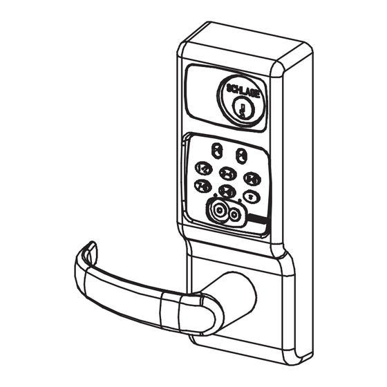
The 5100 series lock is a stand-alone, microprocessor controlled, electro-
mechanical locking system. The 5100 employs a heavy-duty mechanical
design which is easy to install and highly reliable. The FSE and FSA sole-
noid-driven models are hard-wired to a 12 or 24 volt (AC or DC) power
supply. They offer fail secure and fail safe operation,
respectively.Operationally, the outside lever is normally locked and the
inside lever is always free to allow egress. Electronic access control is
achieved by entering an "Access Credential" (magnetic stripe card, code,
iButton Key, or HID Prox fob or card). Electronic access control capabilities
are listed below by model. All models are designed to accommodate an
emergency mechanical key override. Standard features of the CM models
include up to 1000 user memory, real time features including time zones
and holidays, and audit trail of up to 1000 events. Optional ATK (audit trail
- key override) will note any use of the mechanical key on the audit trail
report. Manual and computer programming is supported by all models
which have a keypad. The PRO models are manually programmed to
accept up to 100 codes.
Functions:
5190: Office Function - has "Lock" and "Unlock" buttons on inside
escutcheon - function not available on PRO
5195: Dormitory/Privacy Function - Pushing the "PRIVACY ON" button on
the inside escutcheon places lock in the "Privacy" mode: a "Lockout" cre-
dential or mechanical key is required to enter. Condition is cleared when
the door is opened. Function not available on PRO
5196: Storeroom/Classroom Function - can be unlocked by "toggle" cre-
dential and relocked again by same. See programming guide for more
information.
Models:
FSA:
Solenoid operated clutch - fail safe
FSE:
Solenoid operated clutch - fail secure
KPI:
iButton reader and keypad
IBO:
iButton reader only
MGK: Magnetic stripe card reader, iButton reader and keypad
MGI:
Magnetic stripe card reader and iButton reader
PXK:
Prox card reader, iButton reader, and keypad
PXI:
Prox card reader and iButton reader
PRO:
Keypad only - no computer programming, 100 code memory
Options:
ATK:
Audit trail of mechanical key use (not available on PRO)
HSS:
High security screws on inside escutcheon
SLB:
2-3/4" backset, 1/2" latch bolt
OLB:
2-3/8" backset, 1/2" latch bolt
ELB:
2-3/4" backset, 3/4" latch bolt
T3:
Track 3 card reader (data on track 3 must be ABA track 2 format)
- MGI/MGK only
KD:
Keyed Different, includes Schlage Everest cylinder
LC:
Less Cylinder
Form 51116-C
CM5100 COMPUTER MANAGED CYLINDRICAL LOCK
HARD-WIRED (FSE/FSA) INSTALLATION MANUAL
CM5100-FSA-KPI
CM5100-FSE-KPI
CM5100-FSA-MGK
CM5100-FSE-MGK
CM5100-FSA-PXK
CM5100-FSE-PXK
5100 CYLINDRICAL
LOCKSET - STANDARD
CM5100-FSA-IBO
CM5100-FSE-IBO
CM5100-FSA-MGI
CM5100-FSE-MGI
CM5100-FSA-PXI
CM5100-FSE-PXI
PRO5100-FSA
PRO5100-FSE
Advertisement
Table of Contents

Related Manuals for Schlage CM5100-FSA-KPI


Summary of Contents for Schlage CM5100-FSA-KPI
- Page 1 2-3/8” backset, 1/2” latch bolt PRO5100-FSA ELB: 2-3/4” backset, 3/4” latch bolt PRO5100-FSE Track 3 card reader (data on track 3 must be ABA track 2 format) - MGI/MGK only Keyed Different, includes Schlage Everest cylinder Less Cylinder Form 51116-C...
-
Page 2: Before You Begin
CM5100 COMPUTER MANAGED CYLINDRICAL LOCK HARD-WIRED (FSE/FSA) INSTALLATION MANUAL BEFORE YOU BEGIN: Standard units are shipped from the factory to fit 1-3/4” doors. Verify the door thickness. If the door is not 1-3/4” thick, verify that the door thickness option was ordered or consult factory. Hard-wired units (FSE & FSA models) will require that wiring is brought to the door prep. - Page 3 CM5100 COMPUTER MANAGED CYLINDRICAL LOCK HARD-WIRED (FSE/FSA) INSTALLATION MANUAL FSE & FSA MODELS: STANDARD WIRE It is best to have the wire race way prepared at the door and HARNESS THROUGH frame manufacturer. If this has not been done there are two HOLE suggested preparation methods for making wire paths for the FSE and FSA models in the field.
- Page 4 G. Install standoffs. TEST KEY OPERATION NOW: Turning key clockwise until it stops (about 1/2 turn) should allow the lever to turn retractor. RECOMMENDED CAMS: NOTE SCHLAGE EVEREST: P/N B502-948 BLOCKING RING REQUIRED FOR CYLINDER SCHLAGE CLASSIC: P/N B502-191 1-1/8”.
- Page 5 CM5100 COMPUTER MANAGED CYLINDRICAL LOCK HARD-WIRED (FSE/FSA) INSTALLATION MANUAL 3. CHANGE HAND (IF NECESSARY): NOTE: The locks are shipped handed as ordered from factory. If it is necessary to change the hand of the lock, follow the steps below: A. Remove retractor by loosening two 9/64” socket cap screws which attach it to the outside escutcheon. B.
-
Page 6: Door Contact
CM5100 COMPUTER MANAGED CYLINDRICAL LOCK HARD-WIRED (FSE/FSA) INSTALLATION MANUAL 4. INSTALL STRIKE BOX AND STRIKE DOOR CONTACT (INSTALL DOOR CONTACT/MAGNET - CM5195 ONLY - PRIVACY OPTION): DOOR CONTACT MAGNET 5. INSTALL LATCH AND OUTSIDE ESCUTCHEON: A. Install latch into edge of door. Be sure to install it with the beveled edge facing door jamb. B. - Page 7 CM5100 COMPUTER MANAGED CYLINDRICAL LOCK HARD-WIRED (FSE/FSA) INSTALLATION MANUAL 6. INSTALL BASE PLATE ASSEMBLY: Install base plate assembly onto inside of door. (If the door is less than 1-3/4” thick, install spacer between the base plate and the door.) Use socket cap screws with washers on upper standoffs and phillips head screws on lower (retractor assem- bly) standoffs.
- Page 8 CM5100 COMPUTER MANAGED CYLINDRICAL LOCK HARD-WIRED (FSE/FSA) INSTALLATION MANUAL 7. CONNECT WIRE HARNESS COMPONENTS (IF ANY): Hard-wired units (FSE and FSA) will have additional wire harness components. If remote release is to be used, connect the RRK harness at this time - refer to instructions included with the kit. WIRING METHOD ‘B: WIRING METHOD ‘A’: MAIN HARNESS...
- Page 9 CM5100 COMPUTER MANAGED CYLINDRICAL LOCK HARD-WIRED (FSE/FSA) INSTALLATION MANUAL 8. INSTALL INSIDE SPINDLE AND INSIDE ESCUTCHEON: A. Tuck main wiring harness (and other wires coming from outside escutcheon) under retaining clip as shown in detail. B. Insert inside spindle with flat side showing. C.
-
Page 10: Operational Test
CM5100 COMPUTER MANAGED CYLINDRICAL LOCK HARD-WIRED (FSE/FSA) INSTALLATION MANUAL OPERATIONAL TEST: TROUBLE SHOOTING: PROBLEM: POSSIBLE CAUSE: 1. Push down and up on inside lever: latch should retract. Inside lever doesn’t Inside spindle not installed retract latch: 2. Push down and up on outside lever. Lever should be disengaged from retractor and door should not No response from key- Wiring harness not plugged...
Need help?
Do you have a question about the CM5100-FSA-KPI and is the answer not in the manual?
Questions and answers